
Related Manuals for PEMTECH PT900-12R


Summary of Contents for PEMTECH PT900-12R
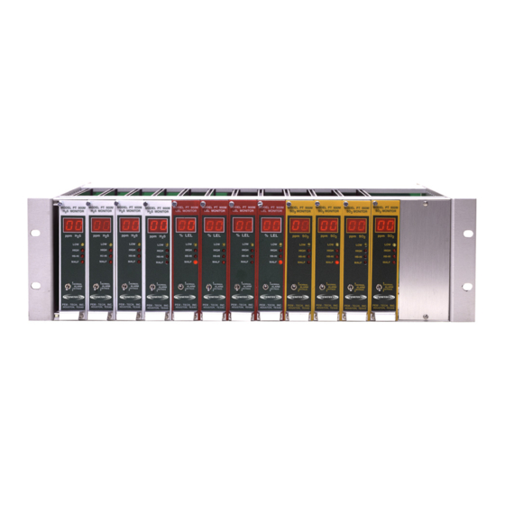
- Page 1 MODEL PT900-12R 12 Channel Gas Monitor & Controller 19” Rack mount Operator’s Manual Revision 3.1 November 2003 Pem-Tech, Inc. Houston, Texas U.S.A.
- Page 2 NOTICE PEM-TECH INCORPORATED SHALL NOT BE LIABLE FOR TECHNICAL OR EDITORIAL ERRORS OR OMISSIONS MADE HEREIN, NOR FOR INCIDENTAL OR CONSEQUENTIAL DAMAGES RESULTING FROM THE FURNISHING, PERFORMANCE, OR USE OF THIS MATERIAL LIMITED WARRANTY Pem-Tech, Incorporated warrants all the equipment to be free from defects in workmanship and material.
- Page 3 SERVICE POLICY Pem-Tech has service facility at the factory. For all the repairs contact at our toll free number 1-800-379-3894 or visit our website www.pem-tech.com For all repairs call us for a Return Material Authorization number (RMA). Inform us briefly the nature of the problem and obtain shipping address. Properly pack the equipment before shipping.
-
Page 4: Table Of Contents
TABLE OF CONTENTS Specifications Specifications for PT900-12R Rack assembly Specifications for Model PT902M Control monitor Overview Programmable Relays Figure 1. PT902M Control module Front Panel diagram Installation and Startup Figure 2. PT900-12R Rack Assembly Setting Control module Address / ID... -
Page 5: Specifications For Pt900-12R Rack Assembly
SPECIFICATIONS For PT900-12 Rack Assembly MOUNTING: Standard 19” Rack mount OPERATING -40 °F to +170 °F. TEMPERATURE POWER INPUT: 24 VDC HUMIDITY: 0 to 100% non condensing AUXILIARY ALARM 4 Common alarm relays RELAYS (Optional) Form “C” type rated 10Amps TERMINATIONS Terminal blocks for sensor and alarm connections for wire size 16-22 AWG... -
Page 6: Specifications For Model Pt902M Control Monitor
SPECIFICATIONS For PT902M Control Module Display Range: 0 to 99 Input Signal: 4-20mA (Optional 1-5 VDC) Analog Output: Linear 4-20mA output. < 1.5mA when remote sensor in malfunction. Maximum of 350 Ohms loop resistance. Relay Ratings: 4 each Form “C” type relay contacts Rated 5 Amps each Low, High, High-High field programmable alarm levels, Latching or non-latching, Normally open or... -
Page 7: Overview
OVERVIEW Pem-Tech model PT902M is a microprocessor based single channel monitor that utilizes the latest digital design techniques in instrumentation. The monitor uses an 8-bit high speed RISC processor with a highly accurate analog to digital logic. The control module receives signal from the remote gas transmitter, displays the gas concentration, and generates 4-20mA analog output. - Page 8 Captive Screw Model PT902M MODEL PT 950 Monitor MONITOR Digital Display HIGH Visual Alarm LED indicators HI−HI MALF Pushbutton switch (Alarm Reset & Adjust) NORMAL ALARMS BYPASS Alarm Bypass Switch PEM−TECH, INC. HOUSTON, TEXAS Handle Figure 1. PT902M Control Module...
-
Page 9: Installation And Startup
INSTALLATION AND START UP Model PT902M Control Module is suitable to mount in a PT900-12R Series Rack assembly with card guides for main circuit board mounting. On the front panel a captive screw is provided to secure the control module to the rack. -
Page 10: Setting Control Module Address / Id
Setting Unit Address ID ***** Skip this section if RS485 or Remote annunciator are not used ****** On PT900-12R Termination board two jumper J1 and J2 located on upper left corner are used for extended module address. Proper jumpers are requied if remote annunciators are connected or RS485 Port is used. -
Page 11: Ac Or Dc Power Input
DC Power Input A two (2) pin wire terminal is provided on the rear termination board for DC power input. The terminal is clearly labeled DC IN. Connect the external DC power to this terminal. Nominal DC power is 24 Volts Refer to figure 3 for the location of the DC IN terminal. - Page 12 HI−HI SENSOR HIGH 4−20 AUX RELAY PORT Figure 3. User termination – PT900-12R Rack assembly...
- Page 13 Figure 4. Remote Sensor connection. Alarm wiring to control modules.
- Page 14 T O A U X . R E L A Y S R E L A Y 1 C O M R E L A Y 2 C O M R E L A Y 3 C O M R E L A Y 4 C O M Figure 5.
-
Page 15: Startup
Start Up Complete the following procedures for the normal unit operation. 1. Complete the mounting and wiring procedures described in earlier sections. 2. Follow gas sensor & transmitter operation manual for proper wiring of sensors with the monitor. 3. Verify all the wiring connections to be correct and secure. 4. -
Page 16: Normal Operation And Alarms
NORMAL OPERATION AND ALARMS Normal Operation During normal operation each control module will display the current gas concentration on the display. If the sensor reading is below alarm level then all the alarm relays and the visual alarm LED indicators on the front panel should be off. -
Page 17: Alarm Bypass
Alarm Bypass In the Alarm Bypass mode the monitor will not activate the alarm relays if any of the sensor reading exceeds the programmed alarm level. However, the visual alarm LED indicators will be activated. To put the alarms in bypass mode move the ALARM toggle switch on the front panel of the control module to BYPASS position. - Page 18 Table I. Range and factory alarm level settings. Control Module Range Low Alarm Hi Alarm Hi-Hi Alarm Level Level Level Hydrogen Sulfide (H2S) 100 ppm 10 ppm (NL) 15 ppm (NL) 20 ppm (NL) Combustible (LEL) 100 % 10 % (NL) 20 % (NL) 30% (NL) Oxygen (O2)
-
Page 19: Programming Alarm Levels
Programming Alarm Levels 1. Move the toggle switch on the front panel to BYPASS position. 2. Press and hold the pushbutton switch (above the toggle switch) until the Low alarm LED starts flashing. Release the switch. 3. While the LED is flashing the display will show the current alarm level. To change the level press and hold the pushbutton switch until the display reads the desired alarm setting. -
Page 20: Setting Alarm Contacts As Normally Open Or
RELAYS LATCHING NON−LATHING 1 2 3 4 Setting alarm contacts as Normally Open or Normally Closed To set the alarm contacts as normally open or normally closed set the jumpers for each relay located right above the relay on the control module. See figure 6. - Page 21 Figure 6. PT902M Control Module...
-
Page 22: Malfunction Condition
The malfunction also occurs if wires connecting the sensors are broken. The fault relay is always non-latching and has a common alarm contact on the PT900-12R termination board. The relay however, can be programmed as normally open or normally closed. -
Page 23: Parts List
Parts List Part Description Number S-760 Auxiliary Relay Board assembly C-720 Blank Cover plates C-587 Replacement card guide C-531 Mini Blue jumper Links C-127 Mini Sensor Fuse PT902M Series Control Modules 902M-H Model PT902M Control Module for H2S sensor (Hydrogen Sulfide) 902M-L Model PT902M Control Module for LEL sensor (Combustible Hydrocarbon)
Need help?
Do you have a question about the PT900-12R and is the answer not in the manual?
Questions and answers