Table of Contents
Advertisement
Quick Links
Advertisement
Table of Contents

Subscribe to Our Youtube Channel
Related Manuals for Duratuf Havelock


Summary of Contents for Duratuf Havelock
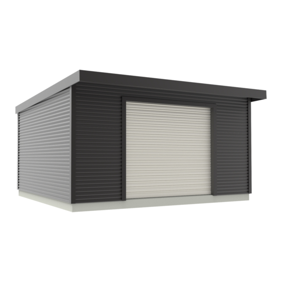
- Page 1 Dura ® LIFESTYLE LIFESTYLE Havelock Assembly Instructions Base size: 4800 x 4200...
-
Page 3: Table Of Contents
Dura ® Contents LIFESTYLE LIFESTYLE Havelock Required tools Before you start Safety precautions Select your site Warranty requirements Parts list Hardware list Base specifications 1. Timber frame assembly 1.1 Back wall assembly 1.2 Side walls assembly 1.3 Front wall assembly 1.4 DPC attachment to bottom plate... -
Page 4: Required Tools
Dura ® Required tools LIFESTYLE LIFESTYLE Havelock Hacksaw Tin snips (left Caulking gun Pipe wrench Riveter & right hand) Utility knife Adjustable spanner Hand saw Hammer Flat file Level • Hex drive 5/16 Cordless drill screwdriver Philips drill bit Square drive drill bit Slotted drill bit •... -
Page 5: Before You Start
Dura ® Before you start LIFESTYLE LIFESTYLE Havelock • Read all instructions carefully. • All dimensions are in millimetres. • 2 people are required for shed install. • Ensure all parts are included and you have access to all required tools. -
Page 6: Parts List
Dura ® Parts list LIFESTYLE LIFESTYLE Havelock Part ID Part name Timber size (mm) Quantity Length Diagram (mm) TB006 Bottom plate-6 (Side) 90x45 4020 TT006 Top plate-6 (Side) 90x45 4020 TB004 Bottom plate-4 (Front+Back) 90x45 4800 TT004 Top plate-4 (Front+Back) - Page 7 Dura ® LIFESTYLE LIFESTYLE Havelock Diagram Part ID Part name Quantity Length (mm) Front wall half sheet-2 4800 Front wall sheet-2 1200 Side wall sheet-1 4200 Back wall sheet-2 4800 Roof sheet-1 4790 Optional clear roof sheet 4790 FDH001 Door head flashing-1...
-
Page 8: Hardware List
Dura ® Hardware list LIFESTYLE LIFESTYLE Havelock Part name Quantity Diagram 30mm clout nails (cladding) 80 pcs 90mm nails (framing) 200 pcs Rivets 80 pcs 25mm Tek Screw (coloured/zinc) 240 pcs 55mm Tek Screw (coloured/zinc) 220 pcs 100mm Tek Screw (coloured/zinc) 20 pcs “L”... -
Page 9: Base Specifications
Dura ® Base specifications LIFESTYLE LIFESTYLE Havelock Use the below specifications to build a concrete base for shed: 4780 Door slope Door slope Door slope 20MPA 100 thick 20MPA 100 thick slab with 200mm slab with 200mm thick perimeter thick perimeter... -
Page 10: Timber Frame Assembly
Dura ® 1. Timber frame assembly LIFESTYLE LIFESTYLE Havelock • Arrange the parts specified in the following steps on a flat surface and attach them together using two 90mm nails at each join. • Studs should be positioned between top and bottom plates. -
Page 11: Back Wall Assembly
Dura ® LIFESTYLE LIFESTYLE 1.1 Back wall assembly Havelock Nail top and bottom plates to end studs. TT004 TB004 Nail remaining studs in correct position. 1131 1154 1154 1131 • Use nogs to get correct spacing. • End nogs may need to be trimmed due to stud thickness. -
Page 12: Side Walls Assembly
Dura ® LIFESTYLE LIFESTYLE 1.2 Side walls assembly Havelock Nail top and bottom plates to end studs. TT006 TB006 Nail remaining studs in correct position. 1154 1154 Nail in nogs at correct height. TN006 TN004 TN004 TN006 •Regarding Part IDs refer to the Parts list in pages 4 & 5. -
Page 13: Front Wall Assembly
Dura ® LIFESTYLE LIFESTYLE 1.3 Front wall assembly Havelock TT004 Nail top and bottom plates to end studs. TB004 Nail remaining studs in correct position. 1061 2492 Nail in nogs at correct height. TN005 TN005 Nail shorter studs each TL001... -
Page 14: Dpc Attachment To Bottom Plate
LIFESTYLE LIFESTYLE 1.4 DPC attachment to bottom plate Havelock Cut pieces of the DPC roll to the length of each wall panel and nail them to underside of bottom plate on wall panels (using 30mm clouts underneath each stud, flush with the outside edge of the bottom plate). -
Page 15: Joining Walls To Each Other
Dura ® LIFESTYLE LIFESTYLE 1.5 Joining walls to each other Havelock Back wall Side wall Side wall Front wall 100mm Tek Screw Side wall Back wall Pre-drill side wall frames as shown using 7mm drill bit. Even spacing Screw frames together using a cordless drill screwdriver and four 100mm Tek Screws at each corner. -
Page 16: Ridge Beam And Door Head Flashing Attachment
LIFESTYLE LIFESTYLE 1.6 Ridge beam and door head flashing Havelock attachment Fix each ridge beam’s 2 ends to the side walls above each stud, using 3 cleats (2 at the top and 1 underneath) and four 25mm Tek Screws, per cleat. -
Page 17: Timber Frame To Base Securement
LIFESTYLE LIFESTYLE 1.7 Timber frame to base securement Havelock Adjust the frame to get a 10mm overhang on all 4 sides. Then, make sure diagonal measurements as shown are the same, to ensure frame is straight and square. Pre-drill a hole within 50mm from one side of studs as shown, through timber and concrete base using hammer drill and 12mm masonry drill bit (18 holes in total). - Page 18 ® LIFESTYLE LIFESTYLE Havelock Ensure diagonal measurements on front wall are the same. Then attach brace strapping in a cross on both left and right sides of the front door, using 30mm nails. Cut bottom plate between door studs using a hand saw (flush with inside of front wall studs).
-
Page 19: Dpc Attachment To Studs
Dura ® LIFESTYLE LIFESTYLE 1.8 DPC attachment to studs Havelock • Using ten 30mm clouts, attach DPC to each corner as shown. DPC should be level with top of top plate and 20mm below bottom of bottom plate. • Repeat above, attaching DPC to door studs with top of DPC level with underside of lintel. -
Page 20: Cladding Attachment
Dura ® 2. Cladding attachment LIFESTYLE LIFESTYLE Havelock External edges: use Tek Screws through every 2 nd trough. Internal edges: use 2 Tek Screws per sheet, per stud. Top & bottom plate: use Tek screws at every stud. Trough Always fasten through 25mm Tek Screw the trough of profile. -
Page 21: Side And Back Walls Cladding Attachment
LIFESTYLE LIFESTYLE 2.1 Side and back walls cladding attachment Havelock • Position first sheet and secure it to timber frame using two 25mm Tek Screws at the top corners (about 30mm back from end of sheet). Top of the sheet to be flush with top of top plate and both ends flush with outside of studs, ensuring bottom of sheet is approximately 850mm down from side top plate (TT006). - Page 22 Dura ® LIFESTYLE LIFESTYLE Havelock Position and attach third sheet. Repeat these steps for remaining back and side walls sheets. Screw the 3 sheets of back and side walls using 25mm Tek Screws in the middle of each sheet (5 screws per end of each sheet and 2 in the middle).
-
Page 23: Front Wall Cladding Attachment
Dura ® LIFESTYLE LIFESTYLE 2.2 Front wall cladding attachment Havelock • Position and attach sheets (as shown in the following steps) to the front wall frame, using three 25mm Tek Screws at each end. • For front wall half sheet, also use 3 screws along the top plate (1 Tek Screw in each 310mm stud). Top of this sheet to be flush with top of the top plate. - Page 24 ® LIFESTYLE LIFESTYLE Havelock Ensure bottom of second row of front wall sheets is approximately 1832mm down from top of front top plate (TT006), and front wall cladding profile height matches side wall profile height. Attach third row of front wall sheets and screw off sheets as per cladding plan.
-
Page 25: Flashing Attachment
Dura ® LIFESTYLE LIFESTYLE 3. Flashing attachment Havelock 3.1 Top plate and door flashing attachment FFT002 Centralise front top plate flashing (FFT002) and attach with four 30mm clouts to top plate. • Position door jamb flashing (FDJ002), so top is level with underside of lintel (TL001). -
Page 26: Corner Flashings Attachment
Dura ® LIFESTYLE LIFESTYLE 3.2 Corner flashings attachment Havelock • Attach corner flashings onto corners using six 55mm Tek Screws per corner, approximately 250mm down from top of the top plate. • Ensure corner flashings are square and parallel with wall panels. -
Page 27: Back Spouting Assembly
Dura ® LIFESTYLE LIFESTYLE 3.3 Back spouting assembly Havelock FBS003 Dropper FS001 • Position dropper anywhere on the back spouting (at least 300mm from either end, centred front and back) and mark diameter of dropper. • Drill a small hole, and using tin snips, cut a larger hole (slightly larger than the diameter of dropper). -
Page 28: Back Spouting Attachment
Dura ® LIFESTYLE LIFESTYLE 3.4 Back spouting attachment Havelock Centralise and nail the assembled spouting to top of the back top plate using four 30mm clouts, so spouting overhangs corner flashings by approximately 25mm at each end. Spouting assembly •... -
Page 29: Roof Sheets Attachment
Dura ® LIFESTYLE LIFESTYLE 4.Roof sheets attachment Havelock 4.1 Layout for fastening roof sheets • Use 55mm Tek Screws to fasten roof sheets. • Always fasten through top of rib of profile. • Use 4 Tek Screws per sheet / top plate / ridge beam. -
Page 30: Roof Sheets Fastening
Dura ® LIFESTYLE LIFESTYLE 4.3 Roof sheets fastening Havelock • Each sheet must correctly overlap the previous sheet. • Sheets must be 480mm past front top plate flashing (FFT002) and overlap back spouting (FBS003). • After fastening all roof sheets, ensure metal filings have been removed from between sheets, and between sheets and fasteners. - Page 31 ® LIFESTYLE LIFESTYLE Havelock Ensure top plate and ridge beams are straight before attaching roof sheets. You may temporarily brace top plates and ridge beams to ensure they are straight, by nailing timber from packaging crate, as shown. Nail to underside if you are using building paper or netting.
- Page 32 Dura ® LIFESTYLE LIFESTYLE Havelock Position and attach second roof sheet ensuring correct overlap and 762mm from edge of previous sheet. • Position and attach remaining roof sheets ensuring correct front overhang and each sheet is 762mm from previous sheet.
-
Page 33: Front Spouting And Barges Attachment
Dura ® LIFESTYLE LIFESTYLE Havelock 5. Front spouting and barges attachment 5.1 Barge support attachment Position barge support flashings (FB007) on each side of shed so bottom of barge support flashing is 190mm below top of ridge beams, parallel with roof slope and centrally between corner flashings. -
Page 34: Barge Flashings And Front Spouting Attachment
Dura ® LIFESTYLE LIFESTYLE 5.2 Barge flashings and front spouting Havelock attachment • Using five 55mm Tek Screws equally spaced per barge, secure barge flashings through roof sheets into the end of ridge beams and top plates. • Attach bottom of barge to barge support using 3 rivets equally spaced per side. - Page 35 Dura ® LIFESTYLE LIFESTYLE Havelock Install the front spouting, and rivet spouting ends to barge flashings at both top and bottom. Then, fasten front spouting to the roof sheets using rivets, equally spaced, 3 rivets per sheet. FFS001 •Regarding Part IDs refer to the Parts list in pages 4 & 5.
-
Page 36: Roller Door Installation
Dura ® LIFESTYLE LIFESTYLE 6. Roller door installation Havelock Series 1 Roll-A-Door Item Description Quantity Rolled plastic wrapped door “A” Style brackets, left and right hand Doors guides, Left and right handed Steel locking bars Small parts bag Guide clips(door size dependant) -
Page 37: Brackets Installation
Dura ® LIFESTYLE LIFESTYLE 6.1 Brackets installation Havelock • Position bracket (B) centre on outer stud, approximately 140mm up from bottom of lintel and 80mm from inside of door opening to outside of bracket. • Mark 2 hole positions using the bracket’s top and bottom slots. -
Page 38: Door Positioning
Dura ® LIFESTYLE LIFESTYLE Havelock 6.3 Door positioning • Rotate the curtain and axle so that the bottom rail of the door is positioned at 3 o`clock. Bottom rail at 3 o`clock • Centralise the curtain on doorway opening. •... -
Page 39: Bottom Rail Stop Attachment
Dura ® LIFESTYLE LIFESTYLE 6.5 Bottom rail stop attachment Havelock • Hook stop behind lip in rail. • Secure the rail from underneath with 6mm screws (G). • Trim weatherseal flush with end of the bottom rail. roll-a-guide bottom rail 6.6 Guides installation... -
Page 40: Handle Fitment
Dura ® LIFESTYLE LIFESTYLE 6.7 Handle fitment Havelock • Fit handle (F) to the outside of the door using the supplied screws (P), nuts, and washers. • Complete drilling holes with 5mm drill bit, through pre-drilled holes on the back of the door. -
Page 41: Troubleshooting
Dura ® LIFESTYLE LIFESTYLE 6.10 Troubleshooting Havelock Symptom Possible cause Remedy a) Check guide clearances. Door is hard to b) Check guides are plumb. Door Jamming in the operate in any c) Check guide surfaces are clean and free from oil. -
Page 42: Spring Tension Adjustment
LIFESTYLE LIFESTYLE 6.11 Spring tension adjustment Havelock WARNING: Ensure that pipe wrench is fitted correctly to axle and it is gripped onto the axle. Do not underestimate the tension in the spring when undoing the clamps. CAUTION: This adjustment requires two persons to perform.
Need help?
Do you have a question about the Havelock and is the answer not in the manual?
Questions and answers