Table of Contents
Advertisement
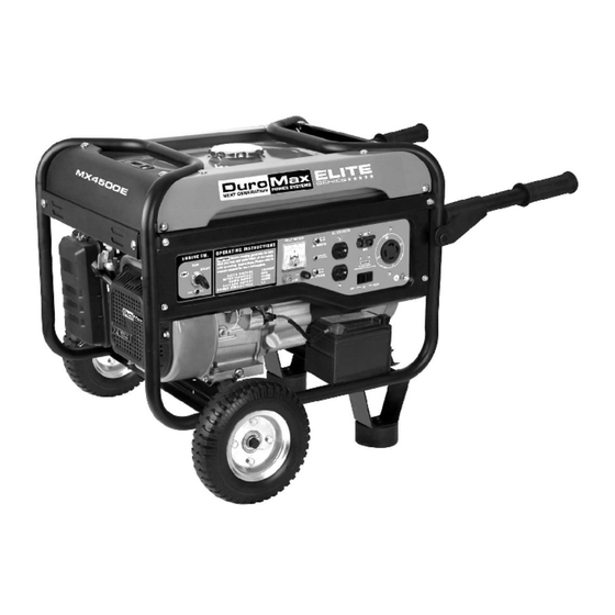
Gasoline Powered Generator
MX4500
MX4500E
Max Tool Customer Service
customer_service@maxtool.com
or call 1-800-629-3325 (option 3) Monday -Thursday 6am to 7pm, Friday - Saturday 6am to 3pm. PST
Product Support
support@maxtool.com
or call 1-800-629-3325 (option 3) Monday -Thursday 6am to 7pm, Friday - Saturday 6am to 3pm. PST
Owner's Manual
(Product: information, application, service info & warranty questions)
Advertisement
Table of Contents

Related Manuals for DUROMAX MX4500


Summary of Contents for DUROMAX MX4500
- Page 1 Gasoline Powered Generator Owner’s Manual MX4500 MX4500E Max Tool Customer Service customer_service@maxtool.com or call 1-800-629-3325 (option 3) Monday -Thursday 6am to 7pm, Friday - Saturday 6am to 3pm. PST Product Support (Product: information, application, service info & warranty questions) support@maxtool.com...
- Page 2 This manual provides information regarding the operation and maintenance of these products. We have made every effort to ensure the accuracy of the information in this manual. We reserve the right to change this product at any time without prior notice. FEATURES •...
-
Page 3: Table Of Contents
TABLE OF CONTENTS GENERAL SAFETY PROCEDURES......................1 PACKAGE CONTENTS ..........................4 GENERATOR COMPONENTS........................5 PREPARING THE GENERATOR FOR USE ....................6 Using the Generator for the First Time....................6 Step 1 – Add Oil ..........................6 Step 2 – Add Gasoline........................7 Step 3 –... -
Page 4: General Safety Procedures
GENERAL SAFETY PROCEDURES Please familiarize yourself with the following safety symbols and words: The safety alert symbol is used with one of the safety words (DANGER, CAUTION, or WARNING) to alert you to hazards. Please pay attention to these hazard notices both in this manual and on the generator. - Page 5 WARNING: This generator produces powerful voltage, which can result in electrocution. ALWAYS ground the generator before using it (see the "Grounding the Generator" portion of the "PREPARING THE GENERATOR FOR USE" section). Generator should only be plugged into electrical devices, either directly or with an extension cord.
- Page 6 In addition to the above safety notices, please familiarize yourself with the safety and hazard markings on the generator.
-
Page 7: Package Contents
PACKAGE CONTENTS Your generator comes with the items listed below. Please check to see that all of the following items may be included with your generator, depending on your generator model. Screwdriver Spanner Spark plug wrench... -
Page 8: Generator Components
GENERATOR COMPONENTS Please familiarize yourself with the locations and functions of the various components and controls of your generator. (1) Air cleaner- a removable, cleanable, sponge-like element that limits the amount of dirt pulled into the engine. (2) Choke lever- Adjusts the amount of air let into the engine. (3) Fuel Gauge- Indicates the amount of fuel in the tank. -
Page 9: Preparing The Generator For Use
This amount, which is equal to the oil capacity of the engine crankcase, can be found on the chart in figure 1. When filling the engine with oil in the future, please refer to this chart. Model number MX4500 MX4500E Engine oil capacity 20 fluid oz. -
Page 10: Step 2- Add Gasoline
Gas can age in the tank and make it hard to start up the generator in the future. Never store generator for extended periods of time with fuel in the tank. Model number MX4500 MX4500E Gas tank capacity 15L(3.96 us. -
Page 11: Subsequent Use Of The Generator
Ground the generator by tightening the grounding nut against a grounding wire (see figure 5). A generally acceptable grounding wire is a No. 12 AWG (American Wire Gauge) stranded copper wire. This grounding wire should be connected at the other end to a copper or brass-grounding rod that is driven into the ground/earth. -
Page 12: Step 3- Ground The Generator
• Do not overfill (check the "Specifications" section for the tank capacity of your generator). Always check for fuel spills. IMPORTANT: • Use only UNLEADED gasoline with an octane rating of 87 or higher. • Do not use old gas. •... -
Page 13: Using The Generator
The surge wattage ability of the generator covers this extra power requirement. Model Number Rated (Running) Wattage Surge Wattage MX4500 3500 4500 MX4500E 3500... - Page 14 If these specifications are not available you may estimate the Watts required by your device by using the chart in figure 10. Tool or Appliance Rated (Running) Watts Additional Surge Watts Electric water heater (40 gal) 4000 Hot plate 2500 Saw-radial arm 2000 2000...
- Page 15 Do not connect 50Hz or 3-phase loads to the generator. Figure 11- Receptacles available on the generator VOLTAGE SELECTOR SWITCH (MX4500/MX4500E) The voltage selector switches the main power carrying windings of the generator to produce "120V ONLY" or "120/240V". If a 240V appliance is connected to the 4-prong receptacle, the switch must be in the "120/240V"...
-
Page 16: Dc Usage
Device Requirements Max. Cord Length (ft) by Wire Gauge Watts Watts Amps #8 wire #10 wire #12 wire #14 wire #16 wire (120V) (240V) 1000 1200 1800 1200 2400 1800 3600 2400 4800 3000 6000 3600 7200 4800 9600 *NR= not recommended Figure 12-Maximum Extension Cord Lengths by Power Requirement DC Usage CAUTION:... -
Page 17: Stopping The Generator
If you perched an electric start model, the battery may not be fully charged, if it doesn’t have sufficient charge to start, the pull start should be used the first time. Running it will charge the battery automatically. While the battery is charging, the charge indication light will shine, after the battery is full charged, the light will turn off. -
Page 18: Checking The Oil
13. When the oil level is low you will need to add oil until the level is sufficient to run the generator. The oil capacity of your generator engine is listed in figure 15 Model number MX4500 MX4500E Engine oil capacity 20 fluid oz. -
Page 19: Air Cleaner Maintenance
It is only necessary to drain the oil from the crankcase if it has become contaminated with water or dirt. In this case, you can drain the oil from the generator according to the following steps: 1. Place a bucket underneath the generator to catch oil as it drains. 2. -
Page 20: Fuel Filter Cup Cleaning
Figure 18- Removing the air cleaner casing. Fuel Filter Cup Cleaning The fuel filter cup is a small well underneath the fuel valve. It helps to trap dirt and water that may be in your fuel tank before it can enter the engine. To clean the fuel filter cup: 1. -
Page 21: Emptying The Gas Tank
5. If you are re-using the spark plug, use a wire brush to clean any dirt from around the spark plug base and then re-gap the spark plug. 6. Screw the spark plug back into its place on the generator using the spark plug wrench. Replace the spark plug cap. -
Page 22: Generator Specifications
GENERATOR SPECIFICATIONS AC Output MX4500 MX4500E Rated Wattage 3500W 3500W Surge Wattage 4500W 4500W Rated Voltage 120/240V 120/240V Rated Frequency 60Hz 60Hz Phase Single Single DC Output MX4500 MX4500E Voltage Amperage 8.3A 8.3A Length=23.2 Length=23.2 Dimensions (in): Width=17 Width=17 Height=17... -
Page 23: Generator Assembly And Mounting
not start Spark plug is broken. Replace spark plug. (continued Move generator to a level surface to Generator is not on level from page prevent low oil shutdown from surface. triggering. Oil is low Add or replace oil. Set the circuit breaker to the “ON” Engine Circuit breaker is off. -
Page 24: Change The Carbon-Brush
Figure 25 Figure 26 Figure 27 Figure 28 CHANGE THE CARBON-BRUSH... -
Page 25: Change The Avr
CHANGE THE AVR... -
Page 26: Wiring Diagram
WIRING DIAGRAM (MX4500) - Page 27 WIRING DIAGRAM (MX4500E)
-
Page 28: Exploded View And Parts List
EXPLODED VIEW AND PARTS LIST (MX4500/MX4500E) Quantity Series Part Code English Name for One Unit Unit ENGN GASOLINE ENGINE Quantity Series Part Code English Name for One Unit Unit CLDH1 DOWEL PIN/10*16 CLDH2 HEAD GASKET CLDH3 BOLT / GB5789-M8*55 CLDH4... - Page 29 KRKS2 BOLT / GB5787-M10*15*1.25 PARONITE GASKET φ10×φ15×1.2 KRKS3 KRKS4 OIL SEAL 25*41.25*6 KRKS5 BEARING / GB276-6205 KRKS6 LOCK PIN/1*5.7 KRKS7 IRON WASHER KRKS8 SHAFT GOVERNOR ARM KRKS9 GOVERNOR GEAR KRKS10 OIL LEVEL SWITCH KRKS11 BOLT / GB5787-M6*16 KRKS12 DOWEL PIN / 8*14 Quantity Series Part Code...
- Page 30 SHFT5 PIN PISTON SHFT6 ROD ASSY CONNECTING Quantity Series Part Code English Name for One Unit Unit KMSHFT1 VALVE EX KMSHFT2 SPRING, VALVE KMSHFT3 RETAINER, EX. VALVE SPRING KMSHFT4 RATATOR VALVE KMSHFT5 VALVE IN KMSHFT6 SEAL GUIDE KMSHFT7 RETAINER, IN. VALVE SPRING KMSHFT8 LIFTER VALVE KMSHFT9...
- Page 31 STR3 STARTER STR4 KNOB SWITCH ASSY ENGINE STOP(OIL STR5 ALERT) STR6 BOLT / GE5787-M6*12 RED PAPER WASHER / STR7 Φ6.2*Φ10*0.8 STR8 REEL RECOIL STARTER STR9 SPRING RECOIL STARTER STR10 RATCHET STARTER STR11 GUIDE RATCHET STR12 SCREW SETTING STR13 COVER STARTER STR14 ROPE Quantity...
- Page 32 KBRTR1 PAPER WASHER ,AIR CLEANER KBRTR2 CARBURETOR KBRTR3 PAPER WASHER, CARBURETOR KBRTR4 INSULATOR CARBURETOR KBRTR5 PAPER WASHER , AIR INTAKE KBRTR6 CHOKE LEVER KBRTR7 CARBURETOR’S NOUMENON Quantity Series Part Code English Name for One Unit Unit FLYWL1 NUT / GB6177-M14 FLYWL2 STARTING FLANGE FLYWL3...
- Page 33 RGLTRA6 SPRING THROTTLE RETURN RGLTRA7 ROD GOVERNOR RGLTRA8 BOLT / GB5787-M6*12 Quantity Series Part Code English Name for One Unit Unit KLNR1 AIR CLEANER KLNR2 AIR CLEANER COVER KLNR3 PRIMARY FOAM ELEMENT KLNR4 FINE MESH FOAM ELEMENT KLNR5 AIR CLEANER PEDESTAL KLNR6 STEADIER KLNR7...
- Page 34 MFLR5 BACK-UP BLOCK MUFFLER MFLR6 BOLT / GB5787-M6*12 MFLR7 ELASTIC RING / GB93-φ8 MFLR8 NUT / GB6170-M8 MFLR9 BOLT / GB5787-M6*12 Quantity Series Part Code English Name for One Unit Unit FUEL TANK COMP METER COMP FUEL METAL CAP FUEL FILTER FUEL TUBE 4*8*145 CLIP / TUBE ATTACHMENT WASHER /6*25*2...
- Page 35 FRM2 FRONT PROTECTING PLATE RUBBER BOTTOM / INCLUDE LEFT FRM3 ONE AND RIGHT ONE FRM4 NUT / GB6177-M8 RUBBER BOTTOM / INCLUDE LEFT FRM5 ONE AND RIGHT ONE FRM6 SIDE PROTECTING PLATE Quantity Series Part Code English Name for One Unit Unit REAR-END COVER OF...
- Page 36 Quantity Series Part Code English Name for One Unit Unit CONTROL PANEL RED GASKET /Φ6.2*Φ10*0.8 BOLT / GB5787-M6*12 SWITCH VOLTAGE METER ASSY CIRCUIT BREAKER SOCKET / EURO-STYLE DC OUTPUT TERMINAL LOW OIL LIGHT PL10 VOLTAGE SWITCH PL11 TWIN SOCKETS PL12 PROTECTOR OPTIONAL :FOR MX4500E ONLY Quantity...
- Page 37 CONTROL PANEL PLE3 (ELECTRIC START) PLE4 LOCK BLOCK OF WIRE PLE5 PLATE SIDE (ELECTRIC START) CHARGE COIL ASSY PLE6 (ELECTRIC START) STARTER COMP PLE7 (ELECTRIC START) PLE8 CHARGING LIGHT...
Need help?
Do you have a question about the MX4500 and is the answer not in the manual?
Questions and answers
Part number for battery