Table of Contents
Advertisement
Quick Links
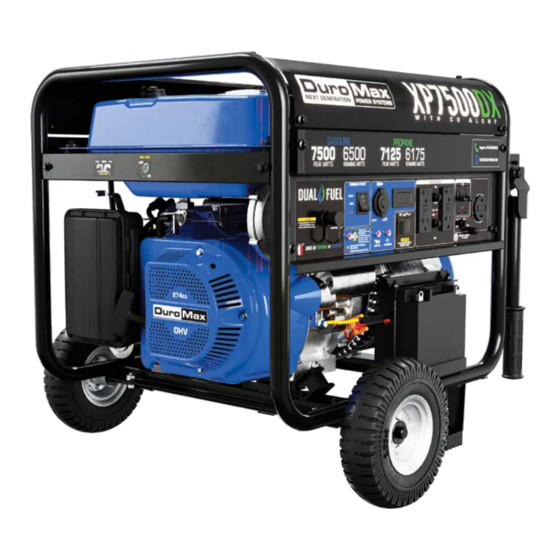
XP7500DX
GENERATOR
User Manual
5800 Ontario Mills Pkwy
Ontario, CA 91764 USA
This manual provides information regarding the operation
www.duromaxpower.com
and maintenance of these products. We have made every
effort to ensure the accuracy of the information in this
Call our Customer Care Team Toll Free 8-5pm PST Mon-Fri
manual. We reserve the right to change this product at
844-DUROMAX
any time without prior notice.
Advertisement
Table of Contents
Troubleshooting

Related Manuals for DUROMAX DUAL FUEL XP7500DX


Summary of Contents for DUROMAX DUAL FUEL XP7500DX
- Page 1 We have made every effort to ensure the accuracy of the information in this Call our Customer Care Team Toll Free 8-5pm PST Mon-Fri manual. We reserve the right to change this product at 844-DUROMAX any time without prior notice.
-
Page 3: Table Of Contents
Introduction Introduction ........................6 General Safety Procedures ................... 8 Carbon Monoxide Safety ..................... 12 Unit and Purchase Information .................. 14 Quick Start Quick Start Guide (Gasoline) ..................16 Quick Start Guide (Propane) ..................18 Generator Components ....................20 Package Contents ......................22 Generator Setup Wheel Kit Installation .................... - Page 4 CONTENTS Maintenance and Care Maintenance Schedule ....................50 Maintenance Log ......................51 Checking the Oil ......................52 Changing the Oil ......................53 Cleaning the Air Filter ....................54 Spark Plug Maintenance ....................56 Cleaning the Fuel Filter Cup ..................58 Storage and Transportation ..................
- Page 6 DUROMAX The DuroMax Way is more than just a brand, it is our understanding and appreciation of just how important power can be to someone without it… DUROMAX FOR HOME DUROMAX FOR WORK DUROMAX FOR PLAY Electricity in our home not...
-
Page 7: Introduction
INTRODUCTION DuroMax Power Equipment is headquartered in Ontario, California and is the industry’s leader in Dual Fuel portable generator technology. In addition to a full assortment of portable generators ranging from digital inverters to large 15,000-watt portable standby units, their product line includes pressure washers, engines, pumps, and accessories. -
Page 8: General Safety Procedures
GENERAL SAFETY PROCEDURES SAFETY ALERT SYMBOL The safety alert symbol is used with one of the safety words (DANGER, CAUTION, or WARNING) to alert you of hazards. Please pay attention to these hazard notices both in this manual and on the generator. Please familiarize yourself with the following safety symbols and words: ●... - Page 9 WARNING: This generator may emit highly flammable and explosive gasoline vapors, which can cause severe burns or even death. A nearby open flame can lead to an explosion even if not directly in contact with gasoline. ● Do not operate near an open flame. ●...
- Page 10 GENERAL SAFETY PROCEDURES In addition to the above safety notices, please familiarize yourself with the safety and hazard markings on the generator. DANGER DO NOT OVERFILL 1.5” THE GAS TANK OVERFILLING CAN RESULT IN A FIRE, EXPLOSION, OR DEATH.
- Page 11 CAUTION HIGH TEMPERATURE DON’T TOUCH HOT EXHAUST DANGER KEEP SAFE DISTANCE BURN RISK CARBON MONOXIDE SAFE DISTANCE DON’T TOUCH...
-
Page 12: Carbon Monoxide Safety
“the silent killer.” CO-ALERT Description The DuroMax CO Alert system was created to protect our customers and their families from dangerous carbon monoxide. Just like the detector for your home the CO Alert tests the air for to keep you safe and healthy. - Page 13 As the only safe way to use a portable generator, taking your generator outside is absolutely mandatory to keep your family safe from carbon monoxide. But there’s even more you can do. By educating yourself about all carbon monoxide risks, you’ll be better prepared to protect your family from this colorless, odorless threat.
-
Page 14: Unit And Purchase Information
UNIT AND PURCHASE INFORMATION Serial Number Serial Number The serial number is located on the engine block, above and to the left of the oil fill. Serial number format The serial number will be shown in two parts. The engine model, followed by the serial number. -
Page 15: Quick Start
QUICK START The Quick Start of your generator is the minimum necessary setup that will get you going as soon as possible. Be sure to read the instructions starting on pg. 25 for full setup instructions. -
Page 16: Quick Start Guide (Gasoline)
QUICK START GUIDE (GASOLINE) Add oil The oil fill cap is located on the lower engine block to the right of the recoil start housing. Remove the oil fill cap and fill with 20 oz of 10w30 oil. Add gasoline The fuel cap is located on top of the fuel tank. - Page 17 Start generator The switch is located on the left side of the front power panel. Press the switch up to the start position to start the generator. Allow the switch to return to the run position once started. Open choke The choke lever is located above the air filter to the left of the recoil start.
-
Page 18: Quick Start Guide (Propane)
QUICK START GUIDE (PROPANE) Add oil The oil fill cap is located on the lower engine block to the right of the recoil start housing. Remove the oil fill cap and fill with 20 oz of 10w30 oil. Turn breaker off The breaker is located on the right side of the front power panel. - Page 19 Close choke The choke lever is located above the air filter to the left of the recoil start. Slide the lever to the left to cut the air supply and allow more fuel into the engine to start. Start generator The engine switch is located on the left side of the front power panel.
-
Page 20: Generator Components
GENERATOR COMPONENTS 5. Fuel Cap 4. Choke Lever 3. Fuel Valve 6. Ground Terminal 2. Air Cleaner 7. Battery 18. Recoil Start 8. Oil Fill and Dipstick 1. Recoil Start – Easy Pull Recoil Start to start the engine without the electric start. 2. - Page 21 16. AC Breaker - 20A resettable breaker to protect the 20A GFCI Receptacle from accidental overload. 17. Power Boost – DuroMax exclusive Power Boost doubles the amperage available in “120v Only” for heavy loads like RV air conditioners. 18. Engine Switch – 3 Position Switch to “Start”, “Run”, or turn “Off” the generator.
-
Page 22: Package Contents
PACKAGE CONTENTS Your generator comes with the items listed below. Please check to see that all of the following items are included with your generator. Double-Sided Spanner Spark Plug Wrench Screw Driver Phillips and slot blade Assorted wrenches used in Used in spark plug screwdriver used for generator generator maintenance and... -
Page 23: Generator Setup
GENERATOR SETUP Proper setup of your generator will get you going as soon as possible while making sure you and your equipment are safe and cared for. -
Page 24: Wheel Kit Installation
GENERATOR SETUP (CONTINUED) Step 1 - Wheel Kit Installation (Optional) Install support legs Secure the support legs to the frame with the provided lock nuts. Install wheel axle Insert wheel axle bolts through the frame and secure with the provided nut and wrenches. Install wheel axle bracket Insert wheel axle bracket bolts through the frame and secure with the provided nut and wrenches. - Page 25 Install wheels Place the wheels onto either side of the axle. Install outside wheel washers Place the other large washers onto each side the axle in front of the wheel. Install cotter pins Place a cotter pin through the hole in each end of the axle and bend it out to secure the wheels.
-
Page 26: Connect The Battery
GENERATOR SETUP (CONTINUED) Step 2 - Connect the Battery Disconnected on arrival The generator battery is disconnected on arrival to prevent discharge or accidental starting in storage and transportation. Locate the cable Locate both loose sides of the battery cable clip. Connect the cable Securely connect the battery cable clip. -
Page 27: Adding Oil
Step 3 - Adding Oil The generator requires engine oil to operate properly. The generator, when new from the package, contains no oil in the crankcase . You must add the proper amount of oil before operating the generator for the first time. This amount is equal to the oil capacity of the engine crankcase: Model Number XP7500DX Engine Oil Capacity... -
Page 28: Adding Gasoline
GENERATOR SETUP (CONTINUED) Step 4 - Adding Gasoline (Optional) Add Gasoline Make sure the generator is on a level surface. Unscrew gas cap and set aside (NOTE: the gas cap may be tight and hard to unscrew). Slowly add unleaded gasoline to the fuel tank. Be careful not to overfill. -
Page 29: Grounding The Generator
Step 5 - Grounding the Generator Attach grounding wire Ground the generator by tightening the grounding nut against a grounding wire. Connect the other end to a copper or brass grounding rod that’s driven into the earth. A generally acceptable grounding wire is a No. 12 AWG (American Wire Gauge) stranded copper wire. -
Page 31: Starting The Generator
STARTING THE GENERATOR If this is not your first time using the generator there are still steps you should take to prepare it for operation each time you use it. IMPORTANT: At this point, you should be familiar with the procedures described in the first portion of this section entitled “GENERATOR SETUP”... -
Page 32: Checking The Oil
BEFORE YOU START YOUR GENERATOR Step 1 - Check the oil Check the oil The generator is equipped with an automatic shutoff to protect it from damage due to low oil. Nonetheless, you should check the oil level of the engine before each use to ensure that the engine crankcase has a sufficient amount. -
Page 33: Check The Gas Level
Step 2 - Check the gas level (Optional) Check fuel level If running the engine on gasoline check to see that there is sufficient gasoline in the fuel tank. The fuel gauge on top of the tank will give a rough estimate of the gasoline level. The gauge will appear white then fill red as the tank is filled. -
Page 34: Starting The Generator Using Gasoline
STARTING THE GENERATOR Starting the Generator Using Gasoline Shut breaker off The breaker is located on the right side of the front power panel. Flip the breaker down to prevent accidental load when starting the generator. Turn gas valve on The gas valve is located above the recoil start on the bottom of the fuel tank. - Page 35 Allow switch return to RUN When the engine starts, allow the engine switch to return to the “RUN” position. Open choke Push the choke to the OPEN position as the engine warms up. CAUTION: LPG must be shut off when using gasoline! CAUTION: Gasoline must be shut off when using LPG! CAUTION: Disconnect all electrical loads from the generator before attempting to start!
-
Page 36: Starting The Generator Using Propane
STARTING THE GENERATOR (CONTINUED) STARTING THE GENERATOR (CONTINUED) Starting the Generator Using Propane Turn breaker off The breaker is located on the right side of the front power panel. Flip the breaker down to prevent accidental load when starting the generator. Turn the gas valve off The gas valve is located above the recoil start on the bottom of the fuel tank. - Page 37 Close choke The choke lever is located above the air filter to the left of the recoil start. Slide the lever to the left to cut the air supply and allow more gas into the engine to start. Start the generator The engine switch is located on the left side of the front power panel.
-
Page 38: Starting The Generator Using Recoil Start
STARTING THE GENERATOR (CONTINUED) Starting the Generator Using Propane WARNING: WHEN USING THE GENERATOR WITH LPG, MAKE SURE THERE IS NO POSSIBLE IGNITION SOURCE CLOSE TO THE GENERATOR. 1. Before using, make sure all of the LPG connectors and hoses are well connected and sealed. - Page 40 STARTING THE GENERATOR (CONTINUED) Starting the Generator Using Recoil Start Shut breaker off The breaker is located on the right side of the front power panel. Flip the breaker down to prevent accidental load when starting the generator. Select your fuel. If using gasoline, see step 2 on pg.
- Page 41 Pull the recoil start The recoil start is located on the left side panel next to the air filter. Pull the recoil handle slowly until resistance is felt, then quickly pull the recoil handle until fully extended. Open choke After the engine has started. Push the choke to the OPEN position as the engine warms up.
-
Page 43: Using The Generator
USING THE GENERATOR If this is not your first time using the generator, there are still steps you should take to prepare it for operation each time you use it. IMPORTANT: At this point, you should be familiar with the procedures described in the first portion of this section entitled “GENERATOR SETUP”;... -
Page 44: Ac Usage
USING THE GENERATOR AC Usage ● You may connect electrical devices running on AC current according to their wattage requirements. ● The chart below shows the rated and surge wattage of your generator according to its model number. ● The rated wattage corresponds to the maximum wattage the generator can output on a continuous basis. - Page 45 Tool or Appliance Rated (Running) Watts Additional Surge Watts Electric water heater (40 gal) 4000 Hot plate 2500 Radial arm saw 2000 2000 Electric Stove 1500 Circular Saw 1500 1500 Air compressor (1 HP) 1500 3000 Window air conditioner 1200 1800 Miter saw 1200...
-
Page 46: Connecting A Load To The Generator
USING THE GENERATOR (CONTINUED) Connecting a load to the generator NOTE: Be sure to attach devices to the correct receptacle (outlet). 120v devices can be directly connected to the 120v ONLY receptacles. ● ● 120v devices can be connected to the 120/240v receptacle using an appropriate adapter. ●... - Page 47 Voltage Selector Switch This generator features Power Boost Technology, which gives the user the ability to double the power in the generator for more heavy duty applications. The voltage selector switches the dual 120v AC windings of the generator to produce “120V ONLY” or “120/240V”. If a 240V appliance is connected to the 4-prong receptacle, the switch must be in the “120/240V”...
-
Page 49: Maintenance And Care
MAINTENANCE AND CARE Proper maintenance and storage of your generator are essential to ensure trouble-free use of your generator when you need it. By following the maintenance and care requirements, you can keep your generator running smoothly and efficiently for years to come. -
Page 50: Maintenance Schedule
MAINTENANCE AND CARE Proper routine maintenance of your generator is essential for safe, economical, and trouble-free operation. It will also help reduce air pollution. WARNING: Improper maintenance, or failure to correct a problem before operation, can cause a malfunction in which you can be seriously injured or killed. Always follow the inspection, maintenance recommendations, and schedules in this instruction manual. -
Page 51: Maintenance Log
MAINTENANCE LOG Date Generator Hours Maintenance Performed... -
Page 52: Checking The Oil
MAINTENANCE AND CARE (CONTINUED) Checking the oil Check the oil The generator is equipped with an automatic shutoff to protect it from damage due to low oil. Nonetheless, you should check the oil level of the engine before each use to ensure that the engine crankcase has a sufficient amount. -
Page 53: Changing The Oil
Changing the oil Worn out or dirty oil does not cool the generator properly and can lead to catastrophic engine damage. In addition to regular oil changes, it is necessary to drain the oil from the crankcase if it has become contaminated with water or dirt. -
Page 54: Cleaning The Air Filter
MAINTENANCE AND CARE (CONTINUED) Cleaning the air filter Routine maintenance of the air cleaner helps maintain proper airflow to the carburetor. Check that the air cleaner is free of excessive dirt after every use. Note: Improper maintenance may cause less air to enter the engine or dirty air to enter the engine causing overheating and engine wear. - Page 55 Inspect cleaner element Inspect the air cleaner element for damage or excess dirt. Replace the air cleaner element with a new one if damaged or dirty. Replace cleaner element Place the air cleaner element in the housing. Attach the air cleaner cover Close the air cleaner clips on the left hand side of the air cleaner.
-
Page 56: Spark Plug Maintenance
MAINTENANCE AND CARE (CONTINUED) Spark Plug Maintenance The spark plug is important for proper engine operation. A good spark plug should be intact, free of deposits, and properly gapped. SPARK PLUG CONSULT MANUAL Improper maintenance may cause reduced fuel economy, BEFORE REMOVING misfires, trouble starting, or damage to the spark plug threads. - Page 57 Measure plug gap Measure the plug gap with a gauge. The gap should be 0.7-0.8 mm (0.028-0.031 in). Clean and re-gap If you are re-using the spark plug, use a wire brush to clean any dirt from around the spark plug base and then re-gap the spark plug.
-
Page 58: Cleaning The Fuel Filter Cup
MAINTENANCE AND CARE (CONTINUED) Storage and Transportation CAUTION: Never place any type of storage cover on the generator while it is still hot. When transporting your generator: Empty the gas tank (see “Emptying the Gas Tank” in the “Maintenance” section). ●... -
Page 59: Specifications
SPECIFICATIONS AC Rated Wattage 6500W AC Surge Wattage 7500W AC Rated Voltage 120/240V AC Rated Frequency 60 Hz AC Phase Single DC Voltage DC Amperage 4.2A Dimensions LENGTH 27in. WIDTH 21in. HEIGHT 20in. Engine Type 4-Stroke OHV Forced-Air Ignition System Non-Contact Transistor Displacement 274cc... -
Page 61: Troubleshooting
TROUBLESHOOTING This section of the manual is to help you troubleshoot problems with your generator. -
Page 62: Basic Troubleshooting
TROUBLESHOOTING Mode Description Engine Switch is “Off” Set engine switch to “run” Fuel Valve is “Closed” Turn fuel valve to “open” Choke is open Close the choke Engine is out of fuel Add fuel Engine will not start Fuel is old or contaminated Change fuel Spark Plug is dirty Clean spark plug... -
Page 63: Changing / Inspecting The Carbon Brushes
Changing / Inspecting the Carbon Brushes The carbon brushes in conjunction with the AVR regulates power from the generator. The carbon brushes are wearable parts and should be inspected every 250 running hours. Remove generator cover Remove the 2 bolts of the generator cover then pull the cover off the generator. - Page 64 TROUBLESHOOTING (CONTINUED) Changing / Inspecting the Carbon Brushes (Cont.) Install new brush Install new carbon brush with bolt. Connect AVR wires Insert and connect the 2 wires from the AVR, be sure to connect + and – correctly. Replace generator cover Replace the back cover of the generator and secure it with the 2 bolts.
-
Page 65: Changing / Inspecting The Avr
Changing / Inspecting the AVR The carbon brushes in conjunction with the AVR regulates power from the generator. If the generator is overheated or overloaded, the AVR may be damaged and require replacement. Remove generator cover Remove the 2 bolts of the generator cover then pull the cover off the generator. - Page 66 TROUBLESHOOTING (CONTINUED) Changing / Inspecting the AVR (Continued) Disconnect wires from brush Remove the 2 wires from the AVR on the carbon brush. Install new AVR Install the new AVR with the 2 bolts. Reconnect wires to brush Insert and connect the 2 wires from the AVR, be sure to connect + and –...
- Page 67 Replace generator cover Replace the back cover of the generator and secure it with the 2 bolts.
-
Page 68: Wiring Diagram
WIRING DIAGRAM... -
Page 70: Warranty
OEM parts. Warranty Limitations DuroMax Power Equipment does not claim or hold any obligation to loss of time, freight charges, use of the product, or any incidental damages from the use of this product. THIS WARRANTY IS IN LIEU OF ALL OTHER WARRANTIES, EXPRESSED OR IMPLIED. - Page 71 Equipment cannot deny warranty solely for the lack of receipts or for your failure to ensure the performance of all scheduled maintenance. As the small off-road engine owner, you should, however, be aware that DuroMax Power Equipment may deny you warranty coverage if your small off-road engine or a part has failed due to abuse, neglect, improper maintenance or unapproved modifications.
- Page 72 If the part fails prior to the first scheduled replacement, the part must be repaired or replaced by DuroMax Power Equipment according to Subsection (4) below. Any such part repaired or replaced under warranty must be warranted for the remainder of the period prior to the first scheduled replacement point for the part.
- Page 73 (iii) Distribution manifold. (6) Catalyst or Thermal Reactor System (i) Catalytic converter. (ii) Thermal reactor. (iii) Exhaust manifold. DuroMax Power Equipment will furnish with each new engine written instructions for the maintenance and use of the engine by the owner...
-
Page 74: Contact Information
CUSTOMER SERVICE Duromax Power Equipment is committed to ensuring that our products perform when they need to. Our generators are your lifeline in the event of an emergency. Should you have any problems, please contact our customer service department: DUROMAX POWER EQUIPMENT... - Page 76 5800 Ontario Mills Parkway Ontario, CA 91764 United States 844-DUROMAX REV: XP7500DX-10082021...
Need help?
Do you have a question about the DUAL FUEL XP7500DX and is the answer not in the manual?
Questions and answers