Table of Contents
Advertisement
Advertisement
Table of Contents

Related Manuals for DUROMAX XP15000EH


Summary of Contents for DUROMAX XP15000EH
- Page 1 MODEL: XP15000EH This manual provides information regarding the operation and maintenance of these products. We have made every effort to ensure the accuracy of the information in this manual. We reserve the right to change this product at any time without prior notice.
- Page 2 INTRODUCTION Congratulations on your selection of a t his generator. We are certain you will be pleased with your purchase of one of the finest generators on the market. We want to help you get the best results from your new generator and to operate it safely. This manual contains all the information on how to do that;...
-
Page 3: Table Of Contents
CONTENTS GENERATOR SAFETY …………………………………………………………………………………………………………………………………………………. 4 IMPORTANT SAFETY INFORMATION ……………………………………………………………………………………………………………………….….4 Operator Responsibility …………………………………………………………………………………………………………………………………….…..4 Carbon Monoxide Hazards ……………………………………………………………………………………………………………………………….….. 4 Electric Shock Hazards ……………………………………………………………………………………………………………………………………….….4 Fire and Burn Hazards ……………………………………………………………………………………………………………………………………….…..4 Refuel With Care ……………………………………………………………………………………………………………………………………………….…..4 SAFETY LABEL LOCATIONS ……………………………………………………………………………………………………………………………….…………5 CONTROLS & FEATURES ………………………………………………………………………………………………………………………………….…… …… 6 COMPONENT &... - Page 4 CONTENTS Safety Precautions ………………………………………………………………………………………………………….………..……………………….…18 MAINTENANCE SCHEDULE ……………………………………………………………………………………………………….………..…………………… 19 REFUELING ………………………………………………………………………………………………………………………….………..………………………… 19 FUEL RECOMMENDATIONS …………………………………………………………………………………………………………………….………..…….. 20 Gasolines Containing Alcohol ……………………………………………………………………………………………………….………..…………… 21 ENGINE OIL LEVEL CHECK …………………………………………………………………………………………………………….………..………………..21 ENGINE OIL CHANGE …………………………………………………………………………………………………………………………………….………...22 OIL FILTER CHANGE ……………………………………………………………………………………………………………………………….………..………. 22 ENGINE OIL RECOMMENDATION ………………………………………………………………………………………………………….………..………. 23 AIR CLEANER SERVICE ……………………………………………………………………………………………………………………….……….…………...23 FOAM AIR FILTER CLEANING …………………………………………………………………………………………………………………….………..…..
-
Page 5: Generator Safety
GENERATOR SAFETY IMPORTANT SAFETY INFORMATION THIS generators are designed for use with electrical equipment that has suitable power requirements. Other uses can result in injury to the operator or damage to the generator and other property. Most accidents can be prevented if you follow all instructions in this manual and on the generator. The most common hazards are discussed below, along with the best way to protect yourself and others. -
Page 6: Safety Label Locations
GENERATOR SAFETY SAFETY LABEL LOCATIONS These labels warn you of potential hazards that can cause serious injury. Read them carefully. If a label comes off or becomes hard to read, contact your THIS servicing dealer for a placement. THIS generator is designed to give safe and dependable service if operated according to instructions. -
Page 7: Controls & Features
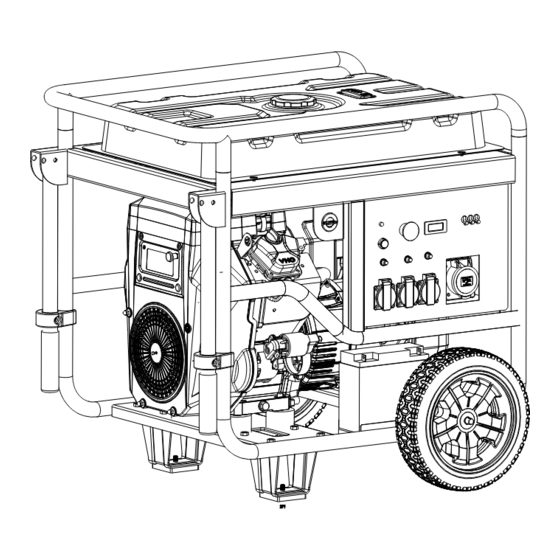
CONTROLS & FEATURES COMPONENT & CONTROL LOCATIONS Use the illustrations on these pages to locate and identify the most frequently used controls. CIRCUIT HOU R BREAKER METER ENGINE SWITCH A C RECEPTACLES CONTROL PANEL... - Page 8 CONTROLS & FEATURES CYLINDER HEAD AIR CLEANER FUEL TAN K CA P EMPTY FULL FUEL GA UG E OIL LEVEL DIPSTICK BATTERY OIL DRAIN TUBE EL ECTR I C STARTER...
-
Page 9: Controls
CONTROLS & FEATURES CONTROLS FUEL VALVE LEVE R Fuel Valve Lever The fuel valve lever is located between the fuel tank and carburetor. The fuel valve lever must be in the ON position for the engine to run. After stopping the engine, turn the fuel valve lever to the OFF position. CHOKE KNOB Choke Knob The choke knob opens and closes the choke valve in the carburetor. -
Page 10: Features
CONTROLS & FEATURES FEATURES Oil Alert System The Oil Alert system is designed to prevent engine damage caused by an insufficient amount of oil in the crankcase. Before the oil level in the crankcase can fall below a safe limit, the Oil Alert system will automatically stop the engine (the engine switch will remain in the ON position). -
Page 11: Before Operation
BEFORE OPERATION ARE YOU READY TO GET STARTED? Your safety is your responsibility. A little time spent in preparation will significantly reduce your risk of injury. Knowledge Read and understand this manual. Know what the controls do and how to operate them. Familiarize yourself with the generator and its operation before you begin using it. -
Page 12: Operation
OPERATION SAFE OPERATING PRECAUTIONS Before operating the generator for the first time, please review the GENERATOR SAFETY section and the chapter titled BEFORE OPERATION. For your safety, do not operate the generator in an enclosed area such as a garage. Your generator’s exhaust contains poisonous carbon monoxide gas that can collect rapidly in an enclosed area and cause illness or death. - Page 13 OPERATION Pull the choke knob to the CLOSED position to start a cold engine. CLOSED Leave the choke knob in the OPEN position to restart a warm engine. CHOKE KNOB 3 -1 . Start the engine. Turn the engine switch to the START position, and hold it there until the engine starts.
-
Page 14: Stopping The Engine
6 The choke operates differently on propane gas. a. If the engine is warm (the unit was run recently) start with the choke half open. i. Wait 30 seconds and then push the choke lever all the way to the "OPEN" position. b. -
Page 15: Ac Operation
OPERATION EN GINE SWICH Turn the engine switch to the OFF position STAR 2-1 . Turn the fuel valve lever to the OFF position. FUEL VALVE LEVER AC OPERATION If an appliance beings to operate abnormally, becomes sluggish or stops suddenly, turn it off immediately. Disconnect the appliance, and determine whether the problem is in the appliance or the rated load capacity of the generator has been exceeded. -
Page 16: Ac Applications
OPERATION AC Applications Before connecting an appliance or power cord to the generator: Make sure that it is in good working order. Faulty appliances or Power cords can create a potential for electrical shock. appliance begins operate abnormally, becomes sluggish, stops suddenly, turn immediately. -
Page 17: Standyby Power
OPERATION total power requirements (VA) appliances connected must considered. Appliance power tool manufacturers usually list rating information near the model number or serial number. STANDBY POWER Connections to a Building’s Electrical System Your generator can supply power to a building’s electrical system. If the generator will be used as an alternative to utility company power, an isolation switch must be installed to disconnect the utility lines from the building when the generator is connected. -
Page 18: Servicing Your Generator
SERVICING YOUR GENERATOR THE IMPORTANCE OF MAINTENANCE Good maintenance is essential for safe, economical, and trouble free operation. It will also help reduce air pollution. To help you properly care for your generator, the following pages include a maintenance schedule, routine inspection procedures, and simple maintenance procedures using basic hand tools. -
Page 19: Maintenance Schedule
SERVICING YOUR GENERATOR Read the instructions before you begin, and make sure you have the tools and skills required. To reduce the possibility of fire or explosion, be careful when working around gasoline. Use only a nonflammable solvent, not gasoline, to clean parts. Keep cigarettes, sparks, and flames away from all fuel related parts. MAINTENANCE SCHEDULE NOTE: (*) Replace the paper element only. -
Page 20: Fuel Recommendations
SERVICING YOUR GENERATOR FUEL TAN K FUEL GAUG E EMPTY FULL Refuel in a well ventilated area before starting the engine. If the engine has been running, allow it to cool. Refuel carefully to avoid spilling fuel. Do not fill the fuel tank above the upper limit mark (red) on the fuel strainer. Never refuel the engine inside a building where gasoline fumes may reach flames or sparks. -
Page 21: Gasolines Containing Alcohol
SERVICING YOUR GENERATOR Gasolines Containing Alcohol If you decide to use a gasoline containing alcohol (gasohol), be sure it’s octane rating is at least as high as that recommended by THIS. There are two types of ‘‘gasohol’’: one containing ethanol, and the other containing methanol. D o not use gasohol that contains more than 10% ethanol. -
Page 22: Engine Oil Change
SERVICING YOUR GENERATOR ENGINE OIL CHANGE Drain the oil while the engine is warm to assure rapid and complete draining. 1. Place the generator on wooden blocks to make space for placing a suitable container. 2. Open the maintenance over to access the oil filler cap. 3. -
Page 23: Engine Oil Recommendation
SERVICING YOUR GENERATOR ENGINE OIL RECOMMENDATIONS Oil is a major factor affecting engine performance and service life. Use 4-stroke automotive detergent oil that meets or exceeds the requirements for API service category SE or later (or equivalent). SAE 10W-30 is recommended for general use. Other viscosities shown in the chart may be used when the average temperature in your area is within the recommended range. -
Page 24: Foam Air Filter Cleaning
SERVICING YOUR GENERATOR NOTICE Operating the engine without an air filter, or with a damaged air filter, will allow dirt to enter the engine, causing rapid engine wear. FOAM AIR FILTER CLEANING A dirty foam air filter will restrict air flow to the carburetor, reducing engine performance. If you operate the generator in very dusty areas, clean the foam air filter more frequently than specified in the Maintenance Schedule. -
Page 25: Spark Plug Service
SERVICING YOUR GENERATOR 2. Clean the sediment cup in nonflammable solvent, and dry them thoroughly. 3. Install the new O-ring and sediment cup, and tighten the sediment cup securely. 4. Make sure there is no fuel leakage. SPARK PLUG SERVICE Recommended spark plugs: F7TC NOTICE An incorrect spark plug can cause engine damage. -
Page 26: Battery Service
SERVICING YOUR GENERATOR NOTICE A loose spark plug can overheat and damage the engine. Over tightening the spark plug can damage the threads in the cylinder head. 7. Attach the spark plug caps. BATTERY SERVICE Your generator’s engine charging system charges the battery while the engine is running. However, if the generator is only used periodically, the battery must be charged monthly to maintain the battery service life. -
Page 27: Battery Charging
SERVICING YOUR GENERATOR This symbol on the battery means that this product must not be treated as household waste. NOTE: An improperly disposed of battery can be harmful to the environment and human health. Always confirm local regulations for battery disposal. Battery Charging The battery is rated at 30.0Ah (ampere hours). -
Page 28: Storage
STORAGE STORAGE PREPARATION Proper storage preparation is essential for keeping your generator trouble free and looking good. The following steps will help to keep rust and corrosion from impairing your generator’s function and appearance, and will make the engine easier to start when you use the generator again. Cleaning Wipe the generator with a moist cloth. -
Page 29: Storage Procedure
STORAGE STORAGE PROCEDURE 1. Drain the fuel tank and carburetor. a. Unscrew the fuel tank cap, remove the fuel filter, and empty the fuel tank into an approved gasoline container. We recommend using a commercially available gasoline hand pump to empty the tank. -
Page 30: Storage Precautions
STORAGE STORAGE PRECAUTIONS If your generator will be stored with gasoline in the fuel tank and carburetor, it is important to reduce the hazard of gasoline vapor ignition. Select a well ventilated storage area away from any appliance that operates with a flame, such as a furnace, water heater, or clothes dryer. -
Page 31: Transporting
TRANSPORTING If the generator has been running, allow the engine to cool for at least 15 minutes before loading the generator on the transport vehicle. A hot engine and exhaust system can burn you and can ignite some materials. Keep the generator level when transporting to reduce the possibility of fuel leakage. Move the fuel valve lever to the OFF position. -
Page 32: Taking Care Of Unexpected Problems
TAKING CARE OF UNEXPECTED PROBLEMS Engine Will Not Start Possible Cause Correction Fuel valve lever OFF. Turn lever ON. 1. Check control positions Choke OPEN. Move to CLOSED Engine switch OFF. Turn engine switch to ON. Out of fuel. Refuel (p.18). 2. -
Page 33: No Power At The Ac Receptacles
TAKING CARE OF UNEXPECTED PROBLEMS No Power at the Possible cause Correction AC Receptacles Circuit breaker left in the OFF position 1. Check circuit breaker. Switch circuit breaker ON. after starting. 2. Check the power tool or Replace or repair power tool or appliance at a known Faulty power tool or appliance. -
Page 34: Technical Information
TECHNICAL INFORMATION SERIAL NUMBER LOCATION ENGINE SERIAL NUMBER DRAIN OIL LINE Record the engine and frame serial numbers and date purchased in the spaces below. You will need this serial number when ordering parts, and when making technical or warranty inquiries. Engine serial number:_____________________________________ Frame serial number:_____________________________________ Date purchased:__________________________________________... -
Page 35: Specifications
TECHNICAL INFORMATION SPECIFICATIONS Dimensions XP15000E Model Length 870 mm Width 588 mm Height 7 26 mm 215kg Dry mass(weight)* *with battery Engine Model DHT720E Engine Type 4-stroke,overheadvalve,2cylinder Displacement 7 13 cc Bore & Stroke 8 0 *71mm Cooling System Forced air Ignition System Transistorized magneto ignition Oil Capacity... -
Page 36: Wiring Diagram
TECHNICAL INFORMATION WIRING DIAGRAM SINGLE PHASE DIAGRAM XP1500E... - Page 38 Product Support Product Information, Application, Service Info & Warranty Questions Please email us at support@duromaxgenerators.com or call (800) 629-3325 Monday – Friday 6:00 am – 6:00 pm (PST)
Need help?
Do you have a question about the XP15000EH and is the answer not in the manual?
Questions and answers
Duromax 1500w Generator My generator is a few years old with less than 25 hours on it. Since new I have had to operate it with the choke pulled all the way out. I run it on lp gas, never tried gasoline. It starts fine with or without the choke. After starting it will run fine with the choke in for five to ten minutes maybe more. Then the speed and voltage drop off significantly. No unusual noises or vibrations. I then have to pull out the choke and run it that way to get the generator up to speed. I have checked out the choke operation and the air filter is like new. My question is, could this be an issue with the IP gas pressure?
Yes, the issue could be related to LP gas pressure. Dual fuel generators 8500 watts or larger, like the DUROMAX XP15000EH, require at least 3 PSI of LP gas pressure to operate properly. Insufficient pressure can affect engine performance, possibly causing it to only run with the choke pulled out.
This answer is automatically generated
@Mr. Anderson Thank you, knowing the required gas pressure helps a lot. I will be checking this out.
Is the idle switch just for gasoline service?
Will a AC Delco PF 53 oil filter fit a XP15000EH generator