Table of Contents
Advertisement
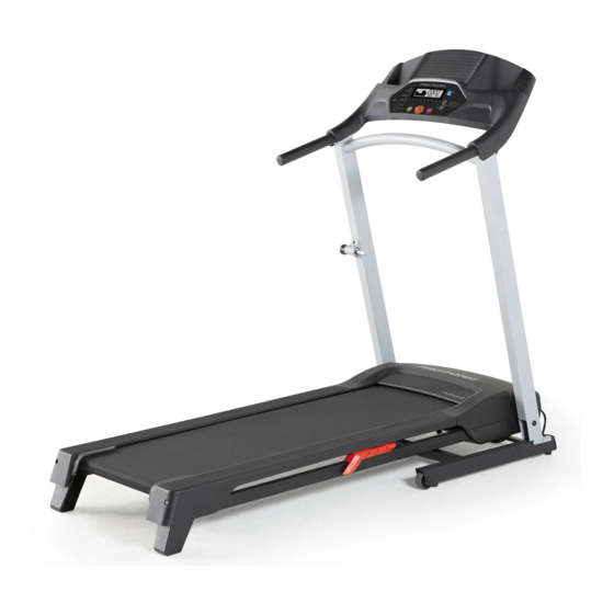
proform.com
Model No. PFTL27721.0
Serial No.
Write the serial number in the space
above for reference.
Serial
Number
Decal
REGISTER YOUR
PRODUCT
To register your product and
activate your warranty today,
go to my.proform.com.
MEMBER CARE
For service at any time, go to
support.proform.com.
Or call 1-833-680-IFIT
(1-833-680-4348)
Mon.–Fri. 6 a.m.–6 p.m. MT
Sat. 8 a.m.–12 p.m. MT
Please do not contact the store.
CAUTION
Read all precautions and
instructions in this manual before
using this equipment. Save this
manual for future reference.
USER'S MANUAL
Advertisement
Table of Contents

Subscribe to Our Youtube Channel
Related Manuals for Pro-Form Cadence LT


Summary of Contents for Pro-Form Cadence LT
- Page 1 proform.com Model No. PFTL27721.0 USER’S MANUAL Serial No. Write the serial number in the space above for reference. Serial Number Decal REGISTER YOUR PRODUCT To register your product and activate your warranty today, go to my.proform.com. MEMBER CARE For service at any time, go to support.proform.com.
-
Page 2: Table Of Contents
TABLE OF CONTENTS WARNING DECAL PLACEMENT ............. . . 2 IMPORTANT PRECAUTIONS . -
Page 3: Important Precautions
IMPORTANT PRECAUTIONS WARNING: To reduce the risk of burns, fire, electric shock, or injury to persons, read all important precautions and instructions in this manual and all warnings on your treadmill before using your treadmill. ICON assumes no responsibility for personal injury or property damage sus- tained by or through the use of this product. - Page 4 17. Keep the power cord and the surge suppres- 25. Do not attempt to move the treadmill until sor away from heated surfaces. it is properly assembled. (See ASSEMBLY on page 8 and HOW TO FOLD AND MOVE 18. Never move the walking belt while the power THE TREADMILL on page 20.) You must be is turned off.
- Page 5 STANDARD SERVICE PLANS...
-
Page 6: Before You Begin
Thank you for selecting the new PROFORM reading this manual, please see the front cover of this ® CADENCE LT treadmill. The CADENCE LT treadmill manual. To help us assist you, note the product model offers a selection of features designed to make your number and serial number before contacting us. -
Page 7: Part Identification Chart
PART IDENTIFICATION CHART Use the drawings below to identify small parts used for assembly. The number in parentheses below each drawing is the key number of the part, from the PART LIST near the end of this manual. The number following the key number is the quantity used for assembly. -
Page 8: Assembly
ASSEMBLY 1. To use the assembly steps in this manual, first see the helpful tips below. • To hire an authorized service technician to • Left parts are marked “L” or “Left” and right parts assemble the treadmill, call 1-800-445-2480. are marked “R”... - Page 9 3. Attach the Left and Right Handrails (71, 72) to the Uprights (76) with four M10 x 45mm Screws (2); start all four Screws, and then tighten them. 4. With the help of a second person, hold the con- sole assembly (A) near the Uprights (76). Insert the Upright Wire (78) through the looped tie (B) on the back of the console assembly (A).
- Page 10 6. Orient the Storage Latch (77) as shown. Attach the Storage Latch to the left Upright (76) with two #10 x 1" Tek Screws (7); start both Tek Screws, and then tighten them. 7. IMPORTANT: You must activate your Console (75) to begin using its exclusive features.
-
Page 11: How To Use The Treadmill
HOW TO USE THE TREADMILL HOW TO CONNECT THE POWER CORD capable of carrying 15 or more amps. To avoid overloading the circuit, do not plug other electrical Use a Surge Suppressor devices, except for low-power devices such as cell phone chargers, into the surge suppressor or into Your treadmill, like other electronic equipment, can be an outlet on the same circuit. - Page 12 CONSOLE DIAGRAM FEATURES OF THE CONSOLE To turn on the power, see page 13. To use the man- ual mode, see page 13. To use an iFIT workout, see IMPORTANT: To activate your console and begin page 15. To connect your heart rate monitor to the using its exclusive features, see assembly step 7 console, see page 16.
- Page 13 HOW TO TURN ON THE POWER HOW TO USE THE MANUAL MODE IMPORTANT: If the treadmill has been exposed to 1. Insert the key into the console. cold temperatures, allow it to warm to room tem- perature before you turn on the power. If you do See HOW TO TURN ON THE POWER at the left.
- Page 14 3. Follow your progress with the display. To manually advance the scan cycle, press the Scan button repeatedly. The display can show the following workout information: To turn off the scan mode, press the Display button; the scan indicator and the word SCAN will Calories (CALS)—The approximate number of turn off.
- Page 15 HOW TO USE AN IFIT WORKOUT 4. Select an iFIT workout. The console offers access to a large and varied library In the iFIT app, touch the buttons at the bottom of of iFIT workouts when you download the iFIT app to the screen to select either the home screen (Home your smart device and connect it to the console.
- Page 16 To pause the workout, simply touch the screen or HOW TO CONNECT YOUR HEART RATE MONITOR press the Stop button. To continue the workout, TO THE CONSOLE press the play icon on the screen, or press the Start button. The console is compatible with all Bluetooth Smart heart rate monitors.
- Page 17 THE SETTINGS MODE Total Distance—The letters MI or KM will appear in the display. The display will show the total 1. Select the settings mode. distance (in miles or kilometers) that the walking belt has moved. To select the settings mode, press the gear button (P).
- Page 18 HOW TO CHANGE THE INCLINE OF THE TREADMILL THE OPTIONAL HEART RATE MONITOR To vary the intensity of your exercise, you can change Whether your the incline of the treadmill. There are two incline levels. goal is to Before changing the incline, remove the key and burn fat or to unplug the power cord.
-
Page 19: Fcc Information
FCC INFORMATION This console has been tested and found to comply with the limits for a Class B digital device, pursuant to part 15 of the FCC Rules. These limits are designed to provide reasonable protection against harmful interference in a residential installation. This equipment generates, uses, and can radiate radio frequency energy and, if not installed and used in accordance with the instructions, may cause harmful interference to radio communications. -
Page 20: How To Fold And Move The Treadmill
HOW TO FOLD AND MOVE THE TREADMILL HOW TO FOLD THE TREADMILL HOW TO MOVE THE TREADMILL Before folding the treadmill, remove the key and Before moving the treadmill, fold it as described at the unplug the power cord. CAUTION: You must be left. -
Page 21: Maintenance And Troubleshooting
MAINTENANCE AND TROUBLESHOOTING MAINTENANCE c. Check the power switch located on the treadmill frame near the power cord. If the switch protrudes Regular maintenance is important for optimal per- as shown (A), the switch has tripped. To reset the formance and to reduce wear. Inspect and properly power switch, wait for five minutes and then press tighten all parts each time the treadmill is used. - Page 22 SYMPTOM: The walking belt slows when walked on SYMPTOM: The walking belt is off-center or slips when walked on a. Use only a surge suppressor that meets all of the specifications described on page 11. a. If the walking belt is off-center, first remove the key and UNPLUG THE POWER CORD.
-
Page 23: Exercise Guidelines
EXERCISE GUIDELINES Aerobic Exercise—If your goal is to strengthen your WARNING: cardiovascular system, you must perform aerobic Before beginning this exercise, which is activity that requires large amounts or any exercise program, consult your physi- of oxygen for prolonged periods of time. For aerobic cian. -
Page 24: Part List
PART LIST Model No. PFTL27721.0 R0721A Key No. Qty. Description Key No. Qty. Description 3/8" x 2 1/4" Screw Warning Decal M10 x 45mm Screw Left Platform Cushion M4.2 x 19mm Screw Right Platform Cushion 1/4" Washer Latch Plate M4 x 13mm Washer Head Screw Latch Plate Spacer M8 x 35mm Screw Belt Guide... -
Page 25: Exploded Drawing
EXPLODED DRAWING A Model No. PFTL27721.0 R0721A... - Page 26 EXPLODED DRAWING B Model No. PFTL27721.0 R0721A 16 18 26 12...
- Page 27 EXPLODED DRAWING C Model No. PFTL27721.0 R0721A...
-
Page 28: Ordering Replacement Parts
ORDERING REPLACEMENT PARTS To order replacement parts, please see the front cover of this manual. To help us assist you, be prepared to provide the following information when contacting us: • the model number and serial number of the product (see the front cover of this manual) •...
Need help?
Do you have a question about the Cadence LT and is the answer not in the manual?
Questions and answers