
Related Manuals for Elenco Electronics M-1000B


Summary of Contents for Elenco Electronics M-1000B
-
Page 1: Digital Multimeter
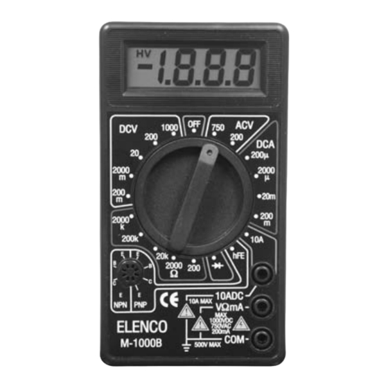
OPERATOR’S INSTRUCTION MANUAL DIGITAL MULTIMETER M-1000B Copyright © 2003 Elenco Electronics, Inc. -
Page 2: Table Of Contents
1. Safety Information 2. Introduction 3. Features 4. Specifications 4-1 General Specifications 4-2 Measurement Specifications 5. Operation 5-1 Preparation and Caution before Measurement 8 5-2 Front Panel Description 5-3 How to Make Measurements 6. Maintenance 6-1 Battery Replacement 6-2 Fuse Replacement PLEASE READ THIS MANUAL CAREFULLY... -
Page 3: Safety Information
• Disconnect the live test lead before disconnecting the common test lead. • To avoid damage to the meter, do not exceed the input limits shown below. • This digital multimeter is designed for indoor use only. FUNCTION INPUT JACK mA, mA DC 10A DC Refer to Section 4-2 on page 6 for complete specifications. -
Page 4: Safety Symbols
CAUTION 500V max. 2. Introduction This meter is a 3 1/2 digit digital multimeter that is rugged, reliable and convenient to use, while providing all of the accuracy and features needed for any application. It performs DC/AC voltage, DC current, resistance, transistor, and diode. -
Page 5: Features
3. Features • 6 Functions / 19 Measuring Ranges • 0.25% Basic Accuracy • 1MW Input Impedance • Overload Protection • Transistor Test • Pocket Size 4. Specifications 4-1. General Specifications Display Polarity Overrange Indication Operation Temperature Power Battery Life (typical) Dimensions Weight Accessories... -
Page 6: Measurement Specifications
4-2. Measurement Specifications Accuracy of specifications apply for 1 year after purchase when operated in a temperature of 18 relative humidity of less than 75%. Basic electrical specifications are given as +([% of reading] + [number of least significant digits]). DC Voltage Range Resolution... -
Page 7: Diode Test
Resistance Range Resolution 200W 20kW 200kW 2000kW OVERLOAD PROTECTION: 15 seconds maximum 220Vrms on all ranges. MAXIMUM OPEN CIRCUIT VOLTAGE: 2.8V. TR h Range Test Condition DIODE TEST Measures forward resistance of a semiconductor junction in kW at max. test current of 1.5mA. 0.1W 100W 10mA DC... -
Page 8: Operation
5. Operation 5-1. Preparation & Caution Before Measurement 1. The function switch should be set to the range to be measured before operation. If the function must be switched during a measurement, always remove the test leads from the circuit being measured. 2. -
Page 10: How To Make Measurements
5-3. How to Make Measurements WARNING 1. To avoid electrical shock hazard and/or damage to the meter, do not measure voltages that might exceed 500V above earth ground. 2. Before using the instrument, inspect the test leads, connectors, and probes for cracks, breaks, or grazes in the insulation. -
Page 11: Ac Voltage Measurement
AC Voltage Measurement 1. Plug the red test lead into the “V W mA” jack and the black lead into the “COM” jack. 2. Set the RANGE switch to the desired ACV position. 3. Connect the test leads to the device or circuit being measured. -
Page 12: Resistance Measurement
Resistance Measurement 1. Plug the red test lead into the “V W mA” jack and the black test lead into the “COM” jack. 2. Set the RANGE switch to the desired W position. 3. If the resistance being measured is connected to a circuit, turn off the power and discharge all capacitors before measuring. - Page 13 Transistor h 1. Set the RANGE switch to the h 2. Determine whether the transistor is an NPN or PNP- type and locate the Emitter, Base and Collector leads. Insert the leads into the proper holes of the socket on the front panel. 3.
-
Page 14: Maintenance
6. Maintenance Before attempting battery & fuse removal or replacement, disconnect the test leads from any energized circuits to avoid hazard. 6-1. Battery Replacement 1. Remove the two screws on the case cover. Then, detach it from the top case. 2. -
Page 15: Fuse Replacement
Failure to turn off the DMM before installing the battery could result in damage to the meter if the battery is connected to the battery terminal incorrectly. 6-2. Fuse Replacement This meter is provided with a 200mA/250V fuse to protect 200mA, 2000mA, 20mA, 200mA ranges. NOTE: The 10A circuit is not fused. - Page 16 Elenco Electronics, Inc. 150 W. Carpenter Avenue Wheeling, IL 60090 (847) 541-3800 http://www.elenco.com e-mail: elenco@elenco.com...
Need help?
Do you have a question about the M-1000B and is the answer not in the manual?
Questions and answers
CAN I TEST COLD CRANKING AMPS ON TRUCK BATTERY
No, the Elenco M-1000B cannot test cold cranking amps on a truck battery.
This answer is automatically generated