Table of Contents
Advertisement
Quick Links
Advertisement
Table of Contents

Related Manuals for Elenco Electronics M-2665K


Summary of Contents for Elenco Electronics M-2665K
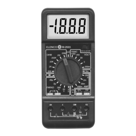
- Page 1 DIGITAL MULTIMETER KIT MODEL M-2665K WIDE RANGE DIGITAL MULTIMETER WITH CAPACITANCE AND TRANSISTOR TESTING FEATURES Assembly and Instruction Manual Elenco™ Electronics, Inc. Copyright © 1991 Elenco™ Electronics, Inc. Revised 2002 REV-P 753005...
-
Page 2: Theory Of Operation
Remember, “An ounce of prevention is worth a pound of cure”. THEORY OF OPERATION A block diagram of the M-2665K is shown in Figure 1. Operation centers around a custom LSI chip. This IC contains a dual slope A/D converter display latches decoder and the display driver. - Page 3 A/D CONVERTER A simplified circuit diagram of the analog portion of the A/D converter is shown in Figure 2. Each of the switches shown represent analog gates which are operated by the digital section of the A/D converter. Basic timing for switch operation is keyed by an external oscillator.
-
Page 4: Voltage Measurement
VOLTAGE MEASUREMENT Figure 3 shows a simplified diagram of the voltage measurement function. The input divider resistors add up 10MW with each step being a division of 10. The divider output should be withing –0.199 to +0.199V or the overload 200mV Volts 900k... -
Page 5: Resistance Measurements
RESISTANCE MEASUREMENTS Figure 5 shows a simplified diagram of the resistance measurement function. External Resistor 900k Figure 5 Simplified Resistance Measurement Diagram A simple series circuit is formed by the voltage source, a reference resistor from the voltage divider (selected by range switches), and the external unknown resistor. -
Page 6: Pin Configuration
TYPICAL SEGMENT OUTPUT 0.5mA Segment Output Internal Digital Ground To Switch Drivers From Comparator Output CLOCK * Three inverters. One inverter shown for clarity. OSC 1 OSC 2 REF HI REF LO C A-Z & A-Z & 10mA IN HI DE (-) DE (+) DE (+) - Page 7 ASSEMBLY The meter kit has been divided into a number of sections to make the assembly easy and avoid major problems with the meter operation. OPEN ONLY THOSE COMPONENT BAGS THAT CALLED IN YOUR PROCEDURE. DO NOT OPEN ANY OTHER BAGS.
-
Page 8: Safety Procedures
CONSTRUCTION Introduction The most important factor in assembling your M-2665 Digital Multimeter Kit is good soldering techniques. Using the proper soldering iron is of prime importance. A small pencil type soldering iron of 25 - 40 watts is recommended. The tip of the iron must be kept clean at all times and well tinned. - Page 9 IDENTIFYING CAPACITOR VALUES Capacitors will be identified by their capacitance value in pF (picofarads), nF (nanofarads), or mF (microfarads). Most capacitors will have their actual value printed on them. Some capacitors may have their value printed in the following manner. The maximum operating voltage may also be printed on the capacitor. Second Digit Multiplier 103K...
- Page 10 RESISTOR READING EXERCISE Before starting assembly of your digital multimeter project, you should be thoroughly familiar with the 5 band color code system. Many of the resistor values will be identified by color bands and it is easy to mistake their value if you read the colors (1) yellow-black-black-black-brown (3) brown-red-violet-red-brown (5) brown-black-black-black-brown...
-
Page 11: Parts Identification
PARTS LIST - SECTION A If any parts are missing or damaged, see instructor or bookstore. DO NOT contact your place of purchase as they will not be able to help you. Contact Elenco™ Electronics (address/phone/e-mail is at the back of this manual) for additional assistance, if needed. Qty. - Page 12 ASSEMBLE THE FOLLOWING COMPONENTS TO THE PC BOARD In all of the following steps the components must be installed on the top legend side of the PC board. The board is turned to solder the component leads on the selector switch side. Figure A Align the notch on the socket (if any) with the notch marked on the PC board.
-
Page 13: Testing Procedure
ASSEMBLE THE LCD Assemble the LCD into the housing with the parts shown in Figure E. The LCD must be put in with the notch in the direction shown in Figure E. Peel off the clear protective film on top of the LCD (see Figure G), then place the LCD plate into the housing with the two curved corners on the inside of the plate in the same direction as the two... - Page 14 PARTS LIST - SECTION B Qty. Symbol Description 1W .5% 1/2W 9W .5% 1/4W 100W .5% 1/4W 900W .5% 1/4W 1.3kW 1% 1/4W 2kW 1% 1/4W 5.6kW 5% 1/4W 8.2kW 5% 1/4W 9kW .5% 1/4W 39.2kW 1% 1/4W 90kW .5% 1/4W 900kW .5% 1/4W 9MW .5% 1/2W 200W / 220W...
- Page 15 ASSEMBLE THE FOLLOWING COMPONENTS TO THE PC BOARD In all of the following steps the components must be installed on the top legend side of the PC board. The board is turned to solder the component leads on the selector switch side. Figure E Stand resistor on end as shown with the body...
- Page 16 Push the four input sockets into the PC board holes from the selector switch side until they stop (see Figure G). Turn the board over as shown in Figure Ga and solder the sockets in place from the top legend side.
- Page 17 PARTS LIST - SECTION C Qty. Symbol Description 5.05kW .5% 1/4W 5.6kW 5% 1/4W R35, 36 5.62kW .5% 1/4W 10kW 5% 1/4W 200kW 5% 1/4W 390kW 5% 1/4W 2.2MW 5% 1/4W Note: Resistor tolerance (last band) of 5-band resistors may be green instead of brown. .1mF (104) .1mF (104) 22mF...
- Page 18 PARTS LIST - SECTION D Symbol Description 1kW Thermister ASSEMBLE THE FOLLOWING COMPONENT TO THE PC BOARD The other components for this section have been installed already. PTC - Thermister 1kW Mount part in holes shown only Testing Procedure Connect the 9V battery and test leads to the meter (red to VW and black to COM).
- Page 19 Capacitance and Transistor Testing Circuit PARTS LIST - SECTION E Qty. Symbol Description 98.8W 1% 1/4W 150W 5% 1/4W 900W 1% 1/4W 1.91kW 1% 1/4W 4.12kW 1% 1/4W 9kW 1% 1/4W 10kW 1% 1/4W 11kW 1% 1/4W R39, R42 39.2kW 1% 1/4W 76.8kW 1% 1/4W 90kW 1% 1/4W 158kW 1% 1/4W...
- Page 20 ASSEMBLE THE FOLLOWING COMPONENTS TO THE PC BOARD In all of the following steps the components must be installed on the top legend side of the PC board. The board is turned to solder the component leads on the selector switch side. R44 - 76.8kW 1% 1/4W Res.
- Page 21 Mount the two 9-pin component sockets to the PC board with the notch at the base of the socket in the direction shown in Figure I. Solder the sockets in place from the top legend side. Component Socket Notch Testing Procedure Connect the 9V battery and test leads to the meter (red to VW and black to COM).
-
Page 22: Final Assembly
FINAL ASSEMBLY Solder the spring to the PC board as shown in Figure Ja. See Figure K for the following steps. Peel off the protective backing on the top plates (A) and (B) and stick them to the top case. Peel off the protective backing on the battery cushion and stick it onto the bottom case. - Page 23 Top Plates Top Case Bearings Ball Bearing Springs Grease Spring Selector Knob Spring Range Selector Knob Battery Shield Plate Bottom Case Figure K Battery Cushion M3 x 12 Screws Stand -22-...
- Page 24 Testing Procedure SECTION C - AC voltage and current circuit Measure an AC voltage with a known accurate meter. Now measure the voltage with the kit meter. The meters should be the same voltage. Connect the kit meter and another meter of known accuracy in series.
-
Page 25: Troubleshooting Guide
TROUBLESHOOTING GUIDE If the meter is not working, perform the U1 (7106R) Voltage Test first. This test is to verify that the IC and Reference Voltage are operational. U1 (7106R) Voltage Test 1. Measure the voltage across pin 40 and pin 15 on U1 (7106R) for 9V. -
Page 26: Battery Low Indicator
Amps Section 1. 200mA scale not working: A. Check fuse. B. Measure across (A) terminal and (COM) terminal for 1W (set meter in 200mA). 1. Lower or higher than 1W, Check R13. 2. 20mA scale not working: A. Check fuse. B. -
Page 27: Using The Digital Multimeter
REINSTALLATION OF THE RANGE SELECTOR KNOB If you removed the range selector knob for troubleshooting, then follow the instructions below to reinstall it. Place the PC board over the range selector knob and fasten the knob to the PC board with a M2.3 x 8 screw. CAUTION: Do not overtighten the screw. -
Page 28: General Specifications
1. FEATURES • Wide measuring ranges: 34 ranges for AC/DC Voltage and Current, Resistance, Capacitance, TR h Diode Test. • 10MW Input Impedance • Big LCD for easy reading • Tilt Stand 2. SPECIFICATIONS 2-1 General Specifications Display 3 1/2 LCD 0.95” height, maximum reading of 1999. Polarity Automatic “–”... - Page 29 AC Voltage Range Resolution 200mV 100mV 10mV 200V 100mV 750V Resistance Range Resolution 200W 0.1W 20kW 200kW 100W 20MW 10kW Maximum open circuit voltage: 2.8V DC Current Range Resolution 200mA 100nA 20mA 10mA 200mA 100mA 10mA AC Current Range Resolution 200mA 100nA 20mA...
-
Page 30: Operation
Transistor h Range Test Condition 10mA 2.8V 10mA 2.8V Diode Test Measures forward resistance of a semiconductor junction in k Ohm at max. test current of 1.5mA. 3. OPERATION 3-1 Preparation and caution before measurement 1. If the function must be switched during a measurement, always remove the test leads from the circuit being measured. -
Page 31: Method Of Measurement
3-3 Method of Measurement (A) DC/AC Voltage Measurement 1. Set the selector switch to “DC” or “AC”. 2. Connect the red test lead to “V/W” input jack and the black one to the “COM” jack. 3. Set the range selector knob to the desired volt position. -
Page 32: (F) Capacitance Measurement
(D) Diode Test 1. Set the selector switch to the “Ohm” position. 2. Connect the red test lead to “V/W” input jack and the black one to the “COM” jack. 3. Set the range selector knob to the “ position. 4. -
Page 33: Battery And Fuse Replacement
4. OPERATION MAINTENANCE 4-1 Battery and Fuse Replacement CAUTION BEFORE ATTEMPTING BATTERY REMOVAL OR REPLACEMENT, DISCONNECT LEADS FROM ANY ENERGIZED CIRCUITS TO AVOID SHOCK HAZARD. The fuse rarely needs replacement and blow almost always as a result of operator error. To replace the battery and fuse (2A/250V), remove the two screws in the bottom of the case. -
Page 34: Schematic Diagram
SCHEMATIC DIAGRAM -33-... - Page 35 QUIZ 1. The function of the A/D converter is to . . . A. convert digital to analog. B. divide analog signal by 2. C. convert analog to digital. D. convert AC to DC. 2. What type of divider network is used for voltage measurements? A.
- Page 36 Elenco™ Electronics, Inc. 150 W. Carpenter Avenue Wheeling, IL 60090 (847) 541-3800 http://www.elenco.com e-mail: elenco@elenco.com...
Need help?
Do you have a question about the M-2665K and is the answer not in the manual?
Questions and answers