Table of Contents
Advertisement
Quick Links
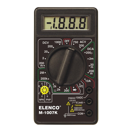
DIGITAL MULTIMETER KIT
MODEL M-1007K
Assembly and Instruction Manual
Elenco
®
Electronics, Inc.
Copyright © 2008 by Elenco
®
Electronics, Inc. All rights reserved.
753096
No part of this book shall be reproduced by any means; electronic, photocopying, or otherwise without written permission from the publisher.
Advertisement
Table of Contents

Related Manuals for Elenco Electronics M-1007K


Summary of Contents for Elenco Electronics M-1007K
- Page 1 DIGITAL MULTIMETER KIT MODEL M-1007K Assembly and Instruction Manual Elenco ® Electronics, Inc. Copyright © 2008 by Elenco ® Electronics, Inc. All rights reserved. 753096 No part of this book shall be reproduced by any means; electronic, photocopying, or otherwise without written permission from the publisher.
-
Page 2: Parts List
PARTS LIST If you are a student, and any parts are missing or damaged, please see instructor or bookstore. If you purchased this meter kit from a distributor, catalog, etc., please contact Elenco ® Electronics (address/phone/e-mail is at the back of this manual) for additional assistance, if needed. RESISTORS (Parts mounted on card.) Qty. -
Page 3: Parts Identification
PARTS IDENTIFICATION Resistors Battery Snap PC Board with IC LCD Assembly Transistor Zebra Clip/Zebra/LCD Socket Zebra Clip Shunt Wire Zebra Fuse Selector Knob Potentiometer Fuse Slide Clip Contact Input Socket Springs Capacitors Ball Bearing Diode Mylar Discap IDENTIFYING RESISTOR VALUES Use the following information as a guide in properly identifying the value of resistors. - Page 4 • Tips should be cleaned frequently to remove oxidation before it becomes impossible to remove. Use Dry Tip Cleaner (Elenco ® #SH-1025) or Tip The most important factor in assembling your M-1007K Digital Multimeter Kit is Cleaner (Elenco ® #TTC1).
- Page 5 ASSEMBLY INSTRUCTIONS Identify and install the following parts as shown. After soldering each part, mark a check þ in the box provided. Be sure that solder has not bridged to an adjacent pad. R15 - 220kΩ 5% 1/4W Resistor R5 - 1kΩ 5% 1/4W Resistor (red-red-yellow-gold) (brown-black-red-gold) (see Figure A)
- Page 6 ASSEMBLY INSTRUCTIONS Identify and install the following parts as shown. After soldering each part, mark a check þ in the box provided. Be sure that solder has not bridged to an adjacent pad. R32 - 2kΩ Thermistor PTC R21 - 900Ω .25% 1/4W Resistor (white-black-black-black-blue) R20 - 100Ω...
- Page 7 r Remove the clear protective film from the Input Sockets front of the LCD as shown in Figure F. Fuse Clips (Note: DO NOT remove the white backing on the other side of the LCD). r Insert the LCD into the case (the tab on Shunt Wire the LCD must be in the same direction shown in Figure G).
- Page 8 r Put the bearings into two opposite indents in the case top as shown in Figure K. r Place the six slide contactors on the selector knobs as shown in Figure K. r Place the selector knob into the case top so that the springs fit over the ball bearings as shown in Figure K. r Place the PC board over the selector knob.
-
Page 9: A/D Converter Calibration
TESTING, CALIBRATION, AND TROUBLESHOOTING TESTING OF LCD With no test leads connected to the meter, move the selector switch around the dial. You should obtain the following readings. A (–) sign may also be present or blinking. 1) ACV Range: HV 0 0 0 3) Ohms, Diode and h Ranges: B indicates blank. -
Page 10: Dc Volts Test
DC VOLTS TEST 1) If you have a variable power supply, set the supply to about the midpoint of each of the DCV ranges and compare the kit meter reading to a meter known accuracy. 2) If you do not have a variable power supply, make the following two tests: a) Set the range switch to 2V and measure the voltage across the 100Ω... -
Page 11: Final Assembly
RESISTANCE/DIODE TEST 1) Measure a resistor of about half of the full scale value of each resistance range. Compare the kit meter readings to those from a meter of known accuracy. 2) Measure the voltage drop of a good silicon diode. You should read about 700mV. Power diodes and the base to emitter junction of power transistors may read less. -
Page 12: Theory Of Operation
THEORY OF OPERATION A block diagram of the M-1007K is shown in Figure 1. Operation centers around a custom LSI chip. This chip contains a dual slope A/D (analog to digital) converter, display latches, seven segment decoder and display drivers. A block diagram of the IC functions is shown in Figure 1. The input voltage or current signals are conditioned by the selector switches to produce an output DC voltage with a magnitude between 0 and 199mV. - Page 13 The integrate period begins at the end of the to be opposite that of the unknown input voltage, autozero period. As the period begins, the AZ switch thus causing the INTEG capacitor to discharge at a opens and the INTEG switch closes. This applies the fixed rate (slope).
-
Page 14: Digital Section
BACKPLANE LCD PHASE DRIVER 7 Segment 7 Segment 7 Segment TYPICAL SEGMENT OUTPUT Decode Decode Decode 0.5mA LATCH Segment Output Tens Units Thousand Hundreds Internal Digital Ground To Switch Drivers From Comparator Output CLOCK 6.2V LOGIC CONTROL TEST Internal Digital Ground 500Ω... -
Page 15: Dc Voltage Measurement
DC VOLTAGE MEASUREMENT 200mV Figure 4 shows a simplified diagram of the DC voltage Volts 900kΩ measurement function. The input voltage divider resistors Low Pass Filter add up to 1 megaohm. Each step down divides the voltage 90kΩ by a factor of ten. The divider output must be within the 7106 range –0.199 to +0.199 volts or the overload indicator will 9kΩ... -
Page 16: Resistance Measurement
RESISTANCE MEASUREMENT Figure 7 shows a simplified diagram of the resistance measurement Low Pass Ω Filter function. A simple series circuit is formed by the voltage source, a 100Ω 7106 reference resistor from the voltage divider (selected by the selector Reference 900Ω... -
Page 17: Meter Operation
METER OPERATION PRECAUTIONS AND PREPARATIONS FOR MEASUREMENT 1) Be sure the battery is connected to the battery snap and correctly placed in the battery compartment. 2) Before connecting the test leads to the circuit, be sure the range switch is set to the correct position. 3) Be sure that the test leads are connected to the correct meter terminals before connecting them to the circuit. -
Page 18: Resistance Measurements
C) 5.05kΩ +.5%. 4. When measuring current, the shunt resistors convert the D) 5.05kΩ +1%. current to . . . 9. The M-1007K has . . . A) –0.199 to +0.199 volts. A) A 3 digit display. B) –1.199 to +1.199 volts. -
Page 19: Schematic Diagram
SCHEMATIC DIAGRAM -18-... - Page 20 Elenco ® Electronics, Inc. 150 Carpenter Avenue Wheeling, IL 60090 (847) 541-3800 Website: www.elenco.com e-mail: elenco@elenco.com 081212...
Need help?
Do you have a question about the M-1007K and is the answer not in the manual?
Questions and answers