Table of Contents
Advertisement
Quick Links
WARRANTY POLICY
Your digital multimeter has been tested and
conforms
to
our
rigid
performance and durability. It is guaranteed to be
free of defects in workmanship, materials and
construction for a period of 2 years. If this
product should fail during normal use within the
first 3 months from the date of purchase,
ELENCO
will repair or replace the unit at no
®
cost. For the remainder of the warranty period, a
nominal service charge is required to cover
shipping and handling.
When returning merchandise for repair, please
include proof of purchase, a brief letter of
explanation of problem and sufficient packing
material.
Before returning any merchandise,
please call our service department at (847) 541-
3800 to obtain a return authorization number (RA).
ELENCO
®
• Service Department
99 Washington Street
Melrose, MA 02176
Phone 781-665-1400
Toll Free 1-800-517-8431
Visit us at www.TestEquipmentDepot.com
requirements
on
OPERATOR'S
INSTRUCTION MANUAL
DIGITAL MULTIMETER
M-1000E
h
Copyright © 2011 ELENCO
®
Advertisement
Table of Contents

Subscribe to Our Youtube Channel
Related Manuals for Elenco Electronics M-1000E


Summary of Contents for Elenco Electronics M-1000E
- Page 1 It is guaranteed to be M-1000E free of defects in workmanship, materials and construction for a period of 2 years. If this product should fail during normal use within the first 3 months from the date of purchase,...
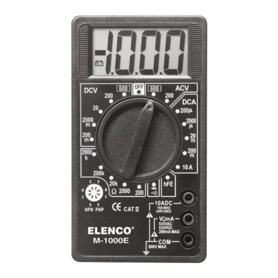
- Page 2 Contents CAUTION 1. Safety Information Failure to turn off the DMM before installing 2. Introduction the battery could result in damage to the meter 3. Features if the battery is connected to the battery 4. Specifications terminal incorrectly. 4-1 General Specifications 4-2 Measurement Specifications 6, 7 6-2.
- Page 3 6. Maintenance 1. Safety Information To ensure that the meter is used safely, follow all of the WARNING safety and operation instructions in this manual. If the Before attempting battery & fuse removal or replacement, meter is not used as described in the manual, the safety disconnect the test leads from any energized circuits to features of the meter might be impaired.
- Page 4 Safety Symbols Transistor h Measurement This marking adjacent to another marking, terminal, or 1. Set the RANGE switch to the h position. operating device indicates that the operator must refer to the explanation in the operating instructions to avoid 2. Determine whether the transistor is an NPN or PNP-type damage to the equipment and/or to avoid personal and locate the Emitter, Base and Collector leads.
- Page 5 Resistance Measurement 3. Features • 7 Functions / 17 measuring ranges 1. Plug the red test lead into the “V Ω mA” jack and the • 0.5% Basic accuracy black test lead into the “COM” jack. • 1MΩ input impedance 2.
- Page 6 AC Current Measurement 4-2. Measurement Specifications Accuracy of specifications apply for 1 year after purchase when 1. Plug the red test lead into the “V Ω mA” jack and the operated in a temperature of 18°C to 28°C (64°F to 82°F) and black lead into the “COM”...
- Page 7 5-3. How to Make Measurements Resistance Range Resolution Accuracy 200Ω 0.1Ω +(0.8% of rdg+2dgt) WARNING 2kΩ 1Ω +(0.8% of rdg+2dgt) 20kΩ 10Ω +(0.8% of rdg+2dgt) 1. To avoid electrical shock hazard and/or damage to the 200kΩ 100Ω +(0.8% of rdg+2dgt) meter, do not measure voltages that might exceed 600V 2000kΩ...
- Page 8 5. Operation 5-1 Preparation & Caution Before Measurement 1. The function switch should be set to the range to be measured before operation. If the function must be switched during a measurement, always remove the test leads from the circuit being measured. 2.
Need help?
Do you have a question about the M-1000E and is the answer not in the manual?
Questions and answers