Table of Contents
Advertisement
Quick Links
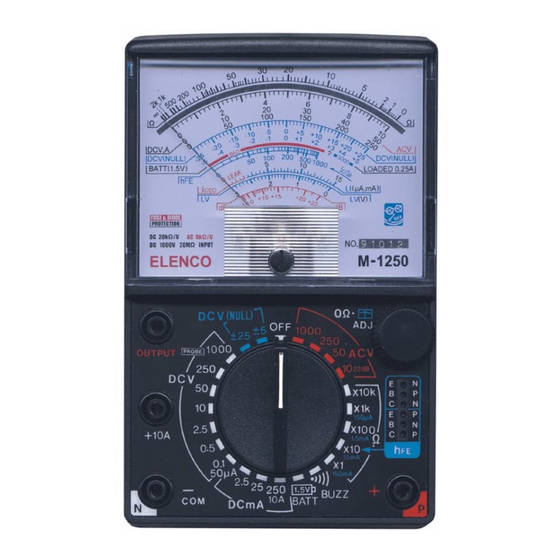
ANALOG MULTIMETER KIT
MODEL M-1250K
Assembly and Instruction Manual
Elenco
®
Electronics, Inc.
Copyright © 2007, 2000 by Elenco
®
Electronics, Inc. All rights reserved.
Revised 2007
REV-H
753070
No part of this book shall be reproduced by any means; electronic, photocopying, or otherwise without written permission from the publisher.
Advertisement
Table of Contents

Subscribe to Our Youtube Channel
Related Manuals for Elenco Electronics M-1250K


Summary of Contents for Elenco Electronics M-1250K
- Page 1 ANALOG MULTIMETER KIT MODEL M-1250K Assembly and Instruction Manual Elenco ® Electronics, Inc. Copyright © 2007, 2000 by Elenco ® Electronics, Inc. All rights reserved. Revised 2007 REV-H 753070 No part of this book shall be reproduced by any means; electronic, photocopying, or otherwise without written permission from the publisher.
-
Page 2: Parts List
PARTS LIST If you are a student, and any parts are missing or damaged, please see instructor or bookstore. If you purchased this kit from a distributor, catalog, etc., please contact Elenco mail is at the back of this manual) for additional assistance, if needed. DO NOT contact your place of purchase as they will not be able to help you. -
Page 3: Specifications
Qty. Symbol D1, D2 Q1, Q3 Qty. Description PC Board Fuse 0.5A, 250V 1.5V Battery 9V Battery Buzzer Selector Knob Zero Adjust Knob Case Bottom Top Cover Assembly Buzzer Case Top Buzzer Case Bottom Selector Wiper Selector Base Screw M4 x 10 Fuse Clip Input Sockets M-1250 Transistor Socket M-1250... - Page 4 CONSTRUCTION Introduction Assembly of your M-1250 Analog Multimeter Kit will prove to be an exciting project and give you much satisfaction and personal achievement. If you have experience in soldering and wiring techniques, then you should have no problem with the assembly of this kit. Care must be given to identifying the proper components and in good soldering habits.
- Page 5 ASSEMBLE COMPONENTS TO THE PC BOARD After each step, put a check in the box located next to the step that you have completed. Place the PC board on a table with the copper side facing up and insert the four input sockets into the PC board holes as shown in Figure A.
- Page 6 ASSEMBLE COMPONENTS TO THE PC BOARD After each step, put a check in the box located next to the step that you have completed. Figure E Mount the 680Ω pot to the PC board as shown. Solder the leads to the foil side of the PC board.
- Page 7 ASSEMBLE COMPONENTS TO THE PC BOARD After each step, put a check in the box located next to the step that you have completed. R28 - 3MΩ 1% 1/2W Resistor (orange-black-black-yellow-brown) C4 - .001μF (102) Capacitor D1 - 2CZ Diode (see Figure D) R24 - 10kΩ...
- Page 8 ASSEMBLE THE BUZZER Tin the buzzer in the three locations shown in Figure Ka. Tin both ends of the 3.5” red, white, and green wires as shown in Figure Kb. Solder the red, white, and green wires to the buzzer (see Figure Kc). Place the buzzer into the holder and snap together (see Figure L).
- Page 9 SOLDER METER MOVEMENT WIRES TO PC BOARD Tin the ends of the meter wires. Solder the red meter wire to M+ and the black wire to M– on the foil side of the PC board (see Figure N). M– M– Figure N Buzzer Assembly Red Wire...
- Page 10 INSTALL BATTERY CLIPS Install the PC board into the case (see Figure O). Align the buzzer holder over the two posts and press it down in place (see Figure O). Install the two single and one double battery clip as shown in Figure O. Solder the red and white wires from the PC board locations 3V+ and 3V–...
-
Page 11: Meter Calibration
CALIBRATION Batteries Install the following parts: 1. Install the 9V and the two 1.5V (AA) batteries as shown in Figure 1. Be sure to observe the polarity markings on the bottom of the battery compartment. 2. Place the thumb wheel knob onto the 0Ω ADJ pot located at the lower right side of the meter dial. Meter Calibration (See Operating and Testing the Multimeter Section for meter operating instructions). - Page 12 INSTALL BACK COVER AND 0Ω ADJ KNOB Install the bottom case and mount into place with an M4 x 10 screw as shown in Figure Q. Place the 0Ω ADJ knob onto the front of the unit on the upper right of the panel. Figure Q M4 x 10 Screw Back Case...
-
Page 13: Troubleshooting Chart
TROUBLESHOOTING CHART This chart lists the condition and possible causes of several malfunctions. If a particular part is mentioned as a possible cause, check that part to see if it was installed correctly. Also, check that part and the parts connected to it for good solder connections. - Page 14 OPERATING AND TESTING THE MULTIMETER CAUTION: When measuring an unknown voltage or current, always start with the range switch set to the highest scale. Then, if necessary, move the range switch down until the meter reads in the middle or right half of the dial.
-
Page 15: Dc Current Test
AC Voltage Test In reading AC voltage, it is necessary to obtain a known source of AC. A 12 volt transformer is preferred. If one is not available, use the 120VAC line. CAUTION: Be very careful when working with 120VAC. Be sure that the range switch is in the 250 or 1000VAC position before connecting the test leads to 120VAC. -
Page 16: Theory Of Operation
Buzzer Test 1. Set the range switch to the BUZZ position. 2. The buzzer will sound if there are 20Ω or less across the leads. DCV (NULL) Test 1. Set the range switch to either the ± 5 or ±25 scale in the DCV (NULL) position. 2. -
Page 17: Ac Voltage Measurement
AC Voltage Measurement Figure 5 shows a simplified diagram of the AC voltage measuring circuit. Two diodes are added to the series resistors to rectify the AC voltage. The input impedance on the AC voltage ranges is 9kΩ per volt. On the 250VAC range, the input impedance is therefore 2MΩ. -
Page 18: Battery Test
Measurement Figure 8 shows a simplified diagram of the h the X10 ohms position and the transistor circuit takes the place of the external resistor in the ohms measurement. The higher the h of the transistor, the more current flows in the external circuit and the lower the effective resistance. - Page 19 SCHEMATIC DIAGRAM M-1250K -18-...
- Page 20 Elenco ® Electronics, Inc. 150 Carpenter Avenue Wheeling, IL 60090 (847) 541-3800 Web site: www.elenco.com e-mail: elenco@elenco.com...
Need help?
Do you have a question about the M-1250K and is the answer not in the manual?
Questions and answers
Bom o valor do kit do multímetro