Table of Contents
Advertisement
Quick Links
Advertisement
Table of Contents

Related Manuals for Black Box ME0010A-VDSL


Summary of Contents for Black Box ME0010A-VDSL
- Page 1 ME0011A-VDSL...
-
Page 2: Table Of Contents
CONTENTS Warranty Information ..............4 Radio and TV Interference............4 CE Notice..................4 FCC Part 68.................. 5 Industry Canada Notice ..............6 Service..................6 General Information..............7 Features..................7 Description..................7 Installation................... 9 Standalone unit installation............9 Rack card installation..............10 Connecting the Twisted-Pair Line Interface........ - Page 3 C.2 VDSL Interface ................23 RJ-45 ..................23 Terminal Block................23 RJ-45 ..................23 DISTANCE CHART, BASED ON 24 AWG (0.5 MM)....24...
-
Page 4: Fcc Part 68
1.3 FCC PART 68 The Model ME0011A-vDSL is not intended to be connected to the public telephone network. Caution This equipment complies with Part 68 of the FCC Rules. Please note the following: — The required Universal Service Order code (USOC) jack: RJ-11C The REN helps you determine the number of devices you can con- nect to your telephone line and still have all of those devices ring... -
Page 5: Industry Canada Notice
3. If your ME0010A-VdSL causes harm to the telephone network, the telephone company may temporarily discontinue your service. If possible, they will notify you in advance, but if advance notice is not practical, you will be notified as soon as possible and will be informed of your right to file a complaint with the FCC. -
Page 6: General Information
2.0 GENERAL INFORMATION Thank you for your purchase of this Black Box product. This product has been thoroughly inspected and tested and is warranted for one year for parts and labor. If any questions or problems arise during installation or use of this product, contact Black Box Technical Support at (724) 746-5500. - Page 7 Figure 1. Typical application The units work together to create a transparent extension between two peered Ethernet LANs. POTS/ISDN calls can be made over a VDSL link without interfering with the data. Figure 1 shows a typical point-to-point application using ME0010A-vDSL units.
-
Page 8: Installation
2. Connect the Ethernet interface (refer to section 3.4, “Connecting the 10/100Base-T Ethernet Interface” on page 12). 3. Connect the power plug (refer to section 3.6, “Connecting Power” on page 14). ME0010A-vDSL ME0011A-vDSL t h e t h e / I S... -
Page 9: Connecting The Twisted-Pair Line Interface
3.3 CONNECTING THE TWISTED-PAIR LINE INTERFACE The ME0011A-vDSL supports communication between two peer Ethernet LAN sites over a distance of up to 6,652 ft (2.03 km) over 24 AWG (0.5 mm) twisted-pair wire. Note Actual distance and link performance may vary depending on the environment and type/gauge of wire used. -
Page 10: Connecting The 10/100Base-T Ethernet Interface
The terminal block connector on the ME0011A-vDSL's twisted pair interface is polarity insensitive and is wired for a two-wire interface. The signal/pin relationships is shown in Figure 5. t h e RING Figure 5. ME0011A-vDSL (Terminal Block) twisted pair line interface. 3.4 CONNECTING THE 10/100BASE-T ETHERNET INTERFACE The shielded RJ-45 port labeled Ethernet is the 10/100Base-T interface. -
Page 11: Connecting The 10/100Base-T Ethernet Port To A Hub
Connecting the 10/100Base-T Ethernet Port to a Hub The ME0011A-vDSL 10/100Base-T interface is configured as DTE (Data Terminal Equipment), just like a 10/100Base-T network interface card in a PC. Therefore, it “expects” to connect to a 10/100Base-T Hub using a straight-through RJ-45 cable. -
Page 12: Connecting Power
The RJ-45 connector in the model ME0010A-vDSL’s POTS/ISDN interface is wired as shown in Figure 9. 1 (no connection) 2 (no connection) 3 (no connection) 4 (2-wire RING) 5 (2-wire TIP) 6 (no connection) 7 (no connection) 8 (no connection) Figure 9. -
Page 13: Configuration
4.0 CONFIGURATION The ME0011A-vDSL has four DIP switches for configuring the unit for a wide variety of applications. This section describes switch locations and explains the different configurations. 4.1 CONFIGURING THE HARDWARE DIP SWITCHES Using a small flat-tip screwdriver, remove the protective cover located on the underside of the ME0011A-vDSL (see Figure 10) Figure 10. - Page 14 Switch toggle Push toggle up for ON position Push toggle down for 1 2 3 4 OFF position Figure 11. DIP switch orientation L i n L i n Switch toggle t i v i t y Push toggle to left for ON position Push toggle to right for...
-
Page 15: Configuring Dip Switch S1
4.2 CONFIGURING DIP SWITCH S1 DIP switch S1 is where you configure the VDSL line rate, symmetric or asymmetric, Ethernet full auto sense capability (100BaseT full or half duplex, 10BaseT full or half duplex) or limited auto sense (only 100BaseT half duplex, 10BaseT full or half duplex). Table 1 summarizes default positions of DIP switches S1-1 through S1-4. - Page 16 Table 3: Symmetric VDSL Line Rates Selection Chart S1-2 S1-3 S1-4 Symmetric Line Rate 12.5 Mbps 16.67 Mbps Table 4: Asymmetric VDSL Line Rates Selection Chart S1-2 S1-3 S1-4 Asymmetric Line Rates DS/US 4.17 Mbps/1.56 Mbps 9.38 Mbps/1.56 Mbps 16.67 Mbps/2.34 Mbps...
-
Page 17: Operation
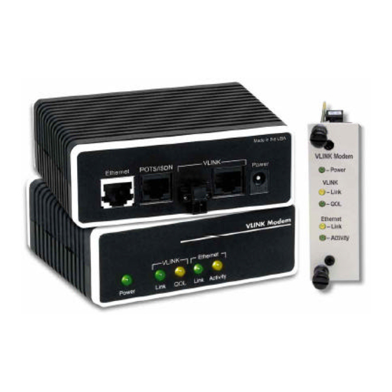
5.0 OPERATION Once the ME0011A-vDSLs are properly installed, they should operate transparently. No user settings required. This section describes reading the LED status monitors. 5.1 POWER UP Before applying power to the ME0011A-vDSL, please review section 3.6, “Connecting Power” on page 14 to verify that the unit is connected to the appropriate power source. - Page 18 Power VLINK Link VLINK QOL L i n Ethernet Link Ethernet Activity L i n i t y t i v Figure 14. rack card front panel Table 5: Front panel LED description Description Power Solid GREEN to indicate the unit is powered on. VLINK Link (Active Green) Solid green (ON) to indicate that the end-to-end VDSL link between the UNITS is...
-
Page 19: Specifications
APPENDIX A SPECIFICATIONS A.1 LAN CONNECTION • Shielded RJ-45, 10/100Base-T, IEEE 802.3 Ethernet • VDSL Connection: RJ-45 and Terminal Block A.2 TRANSMISSION LINE Two-wire unconditioned twisted pair. A.3 VDSL LINE RATE 16.67 Mbps, symmetric upstream/downstream. Additional symmetric and asymmetric rates are available via DIP switch settings. A.4 VDSL DISTANCE 6,000 ft (1.83 km) at 1.56 Mbps upstream/4.17 Mbps downstream Note... -
Page 20: Me0011A-Vdsl Series Interface Pin Assignment
• Pin 5: TIP • Pins 1, 2, 3, 6, 7, 8: no connection Terminal Block See Figure 5 on page 12. C.3 POTS/ISDN INTERFACE ME0010A-vDSL RJ-45 • Pin 4: 2-wire RING • Pin 5: 2-wire TIP • Pins 1, 2, 3, 6, 7, 8: no connection... - Page 21 APPENDIX D DISTANCE CHART, BASED ON 24 AWG (0.5 MM) Symm Line Rate (DS/US) Distance in feet (km) 6.25 Mbps 4,500 (1.37) 9.38 Mbps 4,150 (1.26) 12.5 Mbps 4,000 (1.22) 16.67 Mbps 3,300 (1.00) Asymm Line Rate (DS/US) Distance in feet (km) 4.17 Mbps/1.56 Mbps (Mode 0) 6,000 (1.83) 9.38 Mbps/1.56 Mbps...
Need help?
Do you have a question about the ME0010A-VDSL and is the answer not in the manual?
Questions and answers