Table of Contents
Advertisement
Advertisement
Table of Contents

Subscribe to Our Youtube Channel
Related Manuals for WEEDO X40


Summary of Contents for WEEDO X40
- Page 1 X40 3D Printer User's Guide...
-
Page 2: Table Of Contents
Contents 1.SAFETY WARNINGS AND GUIDELINES ................1 2.INTRODUCTION ........................2 3.FEATURES ..........................2 4.CUSTOMER SERVICE ......................3 5.PACKAGE CONTENTS ......................4 6.PRODUCT OVERVIEW......................5 6.1OverView ........................... 5 7.INTERFACE SYSTEM ....................... 6 7.1 Interface Operation ....................... 6 7.2 Main Interface ........................6 7.3 Select Print File ........................ - Page 3 7.6.8 Nozzle Offset ....................... 22 7.8 Help Interface........................24 8.WIIBUILDER SLICING SOFTWARE ..................25 8.1 Installation........................... 25 8.2 WiiBuilder Setup ........................ 27 8.3 Speed Tab..........................34 8.4 Infill Tab ..........................36 8.5 Support Tab ......................... 38 8.6 Build Plate Adhesion Tab ....................39 8.7 Retraction Tab ........................
-
Page 4: Safety Warnings And Guidelines
1.SAFETY WARNINGS AND GUIDELINES Please read this entire manual before using this device, paying extra attention to these safety warnings and guidelines. Please keep this manual in a safe place for future reference. • Do not reach inside the printer during operation. •... -
Page 5: Introduction
2.INTRODUCTION Thank you for purchasing this X40 3D Printer! This printer uses the FFF (Fused Filament Fabrication) method of printing. It features a metal frame, heated build platform. It can print 1.75mm ABS, PLA, metal fill, wood fill, and other filament types with melting points below 250°... -
Page 6: Customer Service
If you have any problem with your order, please give us an opportunity to make it right. You can contact a WEEDO Customer Service representative through the Live Chat link on our website www.weedo.ltd... -
Page 7: Package Contents
5.PACKAGE CONTENTS Please take an inventory of the package contents to ensure you have all the items listed below. If anything is missing or damaged, please contact WEEDO Customer Service for a replacement. 1x 3D Printer 2x 10m testing PLA filament... -
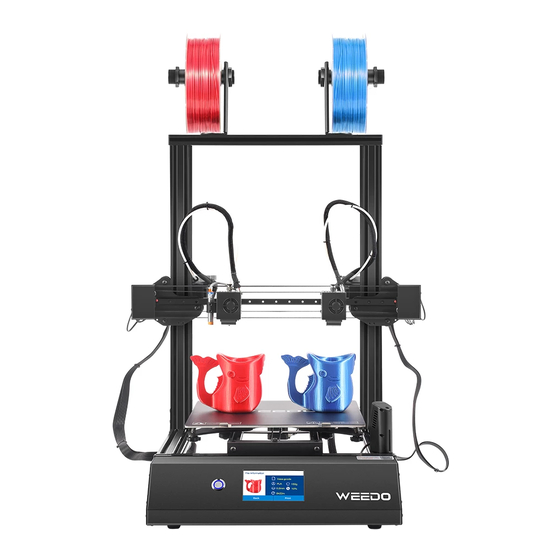
Page 8: Product Overview
6.PRODUCT OVERVIEW 6.1OverView 1. Start button 2. 4.3’’ touch screen 3. TF card port 4. USB port 5. Camera 6. T Type Fixed bracket 7. Nozzle brush 8. Right nozzle 9. Right X motor 10. Right Filament Holder 11. Left Filament Holder 12. -
Page 9: Interface System
7.INTERFACE SYSTEM 7.1 Interface Operation Touch the printer display with your Fingertips. • Enter into the Main interface after Post. • There is a question mark icon in the upper right corner of each interface, this is the help button, you can touch the button, it will show you the functions of icons in the current interface. -
Page 10: Select Print File
7.3 Select Print File Click TF Card and get into TF Print File Interface, choose the Gcode File in the lists. ◆ Return to the Main Interface by clicking Back icon. Click Next icon to see other files ◆ Click the file you selected, you will see the file information in the (Pic7), the picture of the file, File name, filament type, layer height, infill, printing time. -
Page 11: Printing Interface
◆ Click the Back Icon to get into the previous interface(Pic6) 7.4 Printing Interface • The help icon in the upper right corner can help you view a detailed description of the current interface • It shows File Name, Printing Speed, Nozzle Temp, Bed Temp, Printing Elapsed Time, Printing Remain Time, Printing Percent. - Page 12 Pic8 • Click Pause and it will pop up a prompt window (Pic9) and then pause the current print process. After pausing the print process, Filament operation can be used. Pic9 • Click the Question Mark Icon in the upper right corner to display the current interface prompt.
- Page 13 • Click the Filament Operation button, if printing is in progress, this function cannot be used, and it can only be used after printing has been paused (Pic13). Pic13 • Pause the printing process and then click the Filament Operation button(Pic14 Pic15). When your filaments are running out and the model still needs a lot of filaments to print, you can pause and replace the supplies.
-
Page 14: Setting Interface
times, the printing effect on the model surface will become worse. If you want to print faster, set the speed in the slicing software. Pic17 • In this interface you can set the Auto Power Off function (Pic18) on or off, if this function is on, after each printing completed, the device will automatically shut down. -
Page 15: 1Wifi Setting
• Parameters: check parameters, Save firmware parameters to TF card, Load firmware parameters from TF card to printer. 7.5.1WIFI Setting: Pic22 • Connect Wifi: Connect the printer to WIFI. http://www.weedo3dprinter.com/doku.php?id=set_up_wifi_network:x40 Check this wiki file about how to connect the printer to WIFI... -
Page 16: Language
• Machine Info: Check the Information of the WIFI device • Update: When there is a new version of WIFI firmware, Click update, it will begin Firmware OTA update. 7.5.2 Language Select the language you want to show on the interface. 7.5.3 Machine Info: Pic23 •... -
Page 17: Auto Power Off
• Printed Time: The time print has printed, the first time you get the print the printed time may not show zero, do not worry, all of our machine has tested before leaving the factory • Firmware Version: the firmware version of the printer, the firmware version will change after the new firmware is updated. -
Page 18: Post
1 minute, the machine will automatically shut down to save power 7.5.8 Update: If there is a new version of firmware published form WEEDO website or wiki website, you can download it to TF card. The file type is:.wfm and name: flash. -
Page 19: 9Parameters
7.5.9Parameters This interface shows the Firmware parameters of the printer, Home Offset, Z-Probe Offset. If you connect to the computer and do some parameters testing, please save the parameters to TF card, and Load from TF card for the originally parameters if your changed parameters gets wrong printing. -
Page 20: 1Filament Feed
Pic27 • The help icon in the upper right corner can help you view a detailed description of the current interface • Filament Feed: Feed the filament to left and right nozzle. • Filament Retract: Retract the filament of left and right nozzle. •... -
Page 21: 2Filament Retract
Select the nozzle you want to feed filament, after you select the nozzle, for example select the left nozzle, the nozzle starts heating (Pic29), at this time insert the filament into Filament guide tube from extrude. Note: Before inserting the filament into the guide tube, in order to allow the filament to be inserted into the pipe smoothly, straighten the front end of the filament (Picture 30) and then hold the handle of the extruder and insert it from the extruder end. -
Page 22: 3Preheat
Pic33 7.6.3Preheat: Click the Preheat Icon get into Preheat interface (Pic34). In the interface, Nozzle and Bed can be preheated. Choose the target temperature of nozzle and bed and click OK icon, it begins heating, Click the Cancel icon to return to the previous interface. Pic 34 7.6.4 Jog Mode: Click the Jog Mode icon get into Jog Mode interface (Pic35). -
Page 23: Level Bed
Pic35 7.6.5 Level Bed: Click the Level Bed icon get into Level Bed interface (Pic36). Pic36 Prepare a piece of paper, Click Begin icon to enter the leveling process. It will adjust four points. (Pic37-Pic40). Follow the interface prompts to complete the adjustment of each point. Pic 37 Pic38... -
Page 24: Z Offset
Pic 39 Pic40 7.6.6 Z Offset: After Level Bed, Please Click the Z Offset icon to adjust the gap between Nozzle and platform. Note: if the gap is too small, the nozzle will leave deep marks on the platform during printing, which may cause plugging of the print head and damage the nozzle and the platform. -
Page 25: Proximity Height
Click the Down icon the nozzle moves downward, and the gap between the nozzle and the platform becomes smaller, Click the UP icon the nozzle moves up, and the gap between the nozzle and the platform becomes larger, after adjusting to the appropriate gap, click Save icon to save (Pic41). - Page 26 Click X Coarse. Print the two-color test file in the TF card, the file name is: NozzleCoarseTune.gcode At the end of the print, observe the 5 test blocks and select the one with the smallest X deviation as shown in the following figure: select 3 (this example choose 3, depend on the pictures shows on your printer)...
-
Page 27: Help Interface
Horizontal direction: from top to bottom, select the test block with the closest overlap of the two colors in the left and right directions. Choose 5(0) on the model shows. Vertical direction (front and rear direction): from the top down, select the test block with the closest overlap of the two colors in the front and rear direction. -
Page 28: Wiibuilder Slicing Software
8.WIIBUILDER SLICING SOFTWARE The printer includes the WiiBuilder slicing software on the included SD card. Use the included card reader to display the contents of the SD card on your PC to install the program. 8.1 Installation Perform the following steps to install the WiiBuilder slicing software. 1. - Page 29 3. Click the Install button to continue. Pic46 4. Once the installation is complete, click the Next button to continue. Pic47 5. Click the Finish button to complete the installation and launch the program.
-
Page 30: Wiibuilder Setup
8.2 WiiBuilder Setup 1. Once the program launches, the Initial Setup Wizard will launch. It will inform you of several program basics, including how to load model files, the locations of the slice buttons, etc. Read each page, clicking the next button to proceed from page to page. Click the finished button on the final page to close the Wizard. - Page 31 Pic51 4. Click the Advanced tab to display the following dialog. The following sections detail the options on each tab. (Pic52) Pic52 Load STL File. Click File- Open File, select your STL file on your computer. You can select example file also. (Pic53)
- Page 32 Pic53 Slice File: Click Slice, it will slice the file. The bottom left corner of the interface shows the progress of the slice (Pic54), and the bottom right corner of the interface shows the estimated printing time and weight of the printing supplies (Pic55). Note: you can search this website for free stl model: www.thingiverse.com Pic54...
- Page 33 Pic55 Choose Nozzle for single-color model: If you print a single-color model, you can use left or right nozzle. Click ‘edit’ in the right side of interface. Click ‘forearm.stl’ example in Pic56, and in the Material Select the left or right nozzle in the material options. There is a material color option on the right side of the material selection.
- Page 34 Pic57 8. How to color different parts of the movable model. Load a stl file-reno, which is movable show in Pic58, Click ‘Split’, the model will split into different parts, we can choose different nozzle for different parts to print, show in Pic59. When printing two colors, the upper left corner will print the erase tower for switching colors, show in Pic60 Pic58...
- Page 35 Pic59 Pic60 When print dual-color model, you can choose different nozzles to print support and fill. In Pic61, When print dual color, default nozzle is Right Nozzle. When print single color, default nozzle is depending on the nozzle you choose show in pic56.
- Page 36 Pic61 9. How to load two models and merge them together. Load two models simultaneously with the ‘Ctrl’ key on your keyboard. Show in Pic62. Pic62 After the model is loaded into the software, hold down the ctrl key on the keyboard, click the left mouse button to select both models at the same time, then right-click and select ‘Merge Muti-Model’, show in Pic63.
-
Page 37: Speed Tab
Pic63 Pic64 8.3 Speed Tab... - Page 38 Pic65 The Speed Tab features the following options: • Top/Bottom Speed (mm/s): Sets the printing speed of the top and bottom surfaces of the model. • Outer shell speed (mm/s): Sets the printing speed of the external shell surfaces. • Inner shell speed (mm/s): Sets the printing speed of the internal shell surfaces. •...
-
Page 39: Infill Tab
8.4 Infill Tab Pic66 • Infill Pattern: Use the drop-down menu to select one of seven different infill patterns, including Lines, Grid, Triangles, Zig Zag, Concentric, Cross, and Octet. The individual patterns are illustrated in the table below. • Infill Before Wall: Check this box to print the model after filling and printing the outline. - Page 40 Infill Patterns Lines Grid Triangle Zig Zag Concentric Cross Octet...
-
Page 41: Support Tab
8.5 Support Tab Pic67 • Support Pattern: Use the drop-down menu to select one of five support patterns, including Lines, Grid, Triangles, Zig Zag, and Concentric. The pattern designs are the same as those of the infill patterns of the same name. o Lines support is easier to remove and is used on models that require more support. -
Page 42: Build Plate Adhesion Tab
• Support Top: Determines the thickness of the top layer of the supports. • Support Bottom: Determines the thickness of the bottom layer of the supports. • Support Interface: Sets the percentage of infill used inside the supports. • Support Interface Infill Pattern: Use this drop-down menu to choose one of five infill patterns for the supports, including Lines, Grid, Triangles, Zig Zag, and Concentric. - Page 43 Pic70 • Skirt Line Count: Sets the number of anti-overflow lines at the end of the model in contact with the build platform. Pic71...
-
Page 44: Retraction Tab
8.7 Retraction Tab Pic72 • Horizontal Travel Retraction: Check this box to enable filament retraction when the nozzle is not printing and is moving in a horizontal direction. • Retract at Layer Change: Check this box to retract the filament when switching from layer to layer. -
Page 45: Travel Tab
• Filament Diameter (mm): Sets the diameter of the filament being used. This printer only supports 1.75mm diameter filament. 8.9 Travel Tab Pic74 • Combing Mode: This option determines how the nozzle will move when not printing. The Off option has the nozzle move the shortest distance between the previous extrusion location and the new start location. -
Page 46: Machine Tab
8.10 Machine Tab Pic75 • Right Nozzle Diameter (mm): Sets the diameter of the nozzle on the right extruder. This printer only has a single extruder, which is designated the right extruder. The nozzle diameter of this printer is 0.4mm. •... -
Page 47: Dual Extrusion Tab
• Raft Top Line Width (mm): This is the width of the lines in the top surface of the raft. These lines can be thin so that the top of the raft is smooth. • Raft Middle Line Width (mm): This is the width of the lines in the middle raft layers. Making the second layer extrude more causes the lines to stick to the build plate. -
Page 48: Warping Precaution Tab
8.13 Warping Precaution Tab Pic78 • Z Offset (mm): When the Z axis bias is set to negative, the nozzle will print closer to the build platform, which helps reduce warping on large models. • Extra Skin Wall Count: This value sets the number of contours on the outer surface of the model. -
Page 49: Others Tab
o User Specified: This option allows you to specify the X and Y start/stop location, which determines where the Z Seam will appear. o Random: With this option, the printer will randomly choose the start/stop location, which prevents building a column. o Sharpest Corner: The start/stop location and the Z Seam will appear in the sharpest corner of the model. - Page 50 Pic81 Pic82 Pic83 The following image illustrates the print direction of layer three when the Skin Alternate Rotation option is enabled. Pic84 • Enable Print Cooling: When enabled, cooling air will be directed at the printed part. • Enable Draft Shield: When enabled, this printer will print a wall around the model to prevent environmental breezes or drafts from affecting the cooling.
-
Page 51: Specifications
9.SPECIFICATIONS Model Maximum Printing Area 7.9" x 5.9" x 5.9" (300 x 300 x 400 mm) Filament Diameter 1.75mm Nozzle Diameter 0.4mm Printing Speed 20 ~ 150 mm/sec XY Axis: 0.011mm Positioning Accuracy Z Axis: 0.0025mm ABS, PLA, PLA Pro, TPU, TPE, PET, Metal Supported Filament Types fill, Wood fill, etc. -
Page 52: Technical Support
10.TECHNICAL SUPPORT WEEDO is pleased to provide free, live, online technical support to assist you with any questions you may have about installation, setup, troubleshooting, or product recommendations. If you ever need assistance with your new product, please come online to talk to one of our friendly and knowledgeable Tech Support Associates. -
Page 53: Safety Notice
11.SAFETY NOTICE WARNING: Do not use this product near water, for example, in a wet basement or near swimming pool or in an area where accidental contact with water or liquid might occurs WARNING: Avoid using this product during an electrical storm. There may be a remote risk of electric shock from the surge caused by lightning WARNING: The external power adapter or AC power cord is the equipment's disconnection device.
Need help?
Do you have a question about the X40 and is the answer not in the manual?
Questions and answers