Advertisement
Quick Links
Advertisement

Related Manuals for Nautilus HDP6D-LFHR


Summary of Contents for Nautilus HDP6D-LFHR
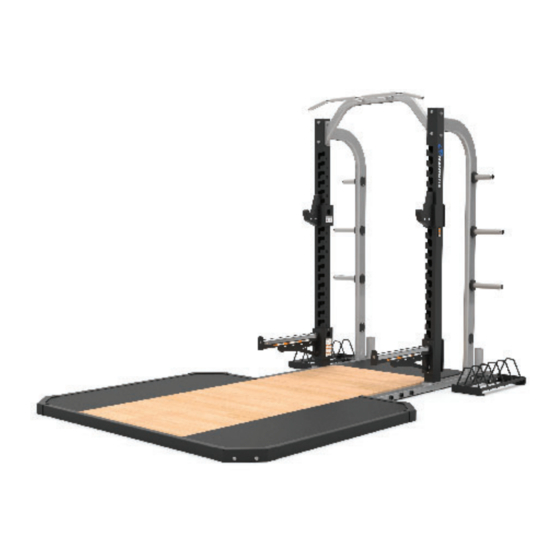
- Page 1 CORE HEALTH & FITNESS HDP6D-LFHR ASSEMBLY MANUAL...
- Page 2 IMPORTANT SAFETY INSTRUCTIONS WARNING! Before using this product, it is essential to read the ENTIRE Owner’s Manual and ALL installation instructions. The Owner’s Manual describes equipment setup and instructs members on how to use correctly and safely. Read all warnings posted on the machine. Health related injuries may result from incorrect or excessive use of exercise equipment.
- Page 3 All equipment MUST be secured (bolted and tightened) to a solid, level surface, using all of the anchoring holes provided, to stabilize and eliminate rocking or tipping over. Shim any mounting surface that does not rest thoroughly on the fl oor using fl at washers, DO NOT force the foot to contact the ground with anchors.
-
Page 4: Important Label Locations
IMPORTANT LABEL LOCATIONS This page shows examples of the warning labels and communication stickers placed on the equipment as part of the manufacturing process. It is critical that own- ers maintain the integrity and placement of these stickers. If you fi nd any stickers missing or damaged the replacement numbers are shown on the support site. See Support and Service to order replacements. - Page 5 ASSEMBLY Required Tools: • 11/16” Open-Ended Wrench • 5/8” Open-Ended Wrench • 3/4” Open-Ended Wrench • 5/16” Allen Key PROCEDURE Insert the tension rod (27-0876) through the backing plate (27-0366) into the rear platform insert. NOTE: Insert and remove the tension rod a few times to ensure it seats all the way and to ensure no debris remains in the rear platform hole.
- Page 6 Use a 11/16” open-ended wrench to tighten the tension rod, securing the rear and center platforms together. Fig. 8 Set the cross-member tube into place against the center platform section. Fig. 9 Assemble the tie rod assembly by inserting two (2) tie rod halves into the tie rod coupling and secure using two (2) pieces of the roll pin.
- Page 7 Insert one tie rod assembly into the cross-member tube set into place in Step 4. Insert the second tie rod assembly into the gap between the rear and center platform sections. Fig. 11 Slide the left side trim tube onto the rear tie rod assembly then install the left side frame tube over the ends of the tie rods.
- Page 8 Use a 5/16” allen key to install the fl oor trim bracket using one (1) piece each of the 1/2” fl at washer and 1/2” -13 x 1’’ button head cap screw. Repeat Step 12 to install a fl oor trim bracket onto the remaining three corners of the frame.
- Page 9 Repeat Step 17 for the left and right sides. Fig. 17 Install the six (6) absorption pads into the platform assembly. Fig. 18 Install the six (6) absorption pad tops with the “NAUTILUS” logo into the platform assembly. Fig. 19 Page 9...
- Page 10 Install the textured rubber platform mats onto the top of the absorption pad tops. Fig. 20 Installation is Complete. Page 10...
- Page 11 SUPPORT & SERVICE For Technical Support, Service, Parts Orders or any Customer Service needs, please contact us direct by phone, email, or through our 24 hour support site: GLOBAL SUPPORT CENTER 4400 NE 77th Avenue, Suite 300 Vancouver, WA 98662 Tel: (360) 326-4090 •...
- Page 12 PART NUMBER 620-8833, REV A All rights reserved. Star Trac, the Star Trac logo and StairMaster are registered trademarks of Core Health & Fitness, LLC. Schwinn and Nautilus are registered trademarks of Nautilus Inc. used under license to Core Health & Fitness LLC. Throwdown is a registered trademark of Throwdown Industries, LLC.
Need help?
Do you have a question about the HDP6D-LFHR and is the answer not in the manual?
Questions and answers