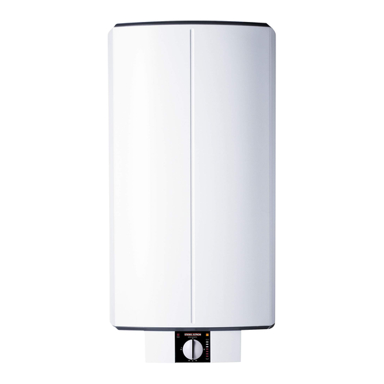
STIEBEL ELTRON SHZ 30 S Operation And Installation
Wall mounted dhw cylinder
Hide thumbs
Also See for SHZ 30 S:
- Operating and installation instructions (24 pages) ,
- Operating and installation instructions (24 pages) ,
- Operating and installation instructions (24 pages)
Summary of Contents for STIEBEL ELTRON SHZ 30 S
- Page 1 OPERATION AND INSTALLATION Wall mounted DHW cylinder » SHZ 30 S (GB) » SHZ 50 S (GB) » SHZ 100 S (GB) » SHZ 150 S (GB)
-
Page 2: Table Of Contents
CONTENTS SPECIAL INFORMATION 16.7 Fault conditions ������������������������������������������������� 13 16.8 Details on energy consumption ������������������������������ 14 OPERATION 16.9 Data table �������������������������������������������������������� 14 General information �����������������������������������������3 GUARANTEE Safety instructions ����������������������������������������������� 3 Other symbols in this documentation ����������������������� 3 ENVIRONMENT AND RECYCLING Units of measurement ������������������������������������������ 3 Safety ����������������������������������������������������������3 Intended use ������������������������������������������������������... -
Page 3: Special Information
SPECIAL INFORMATION | OPERATION General information Other symbols in this documentation - Size the drain so that water can drain off unim- peded when the safety valve is fully opened. Note - Fit the discharge pipe of the safety valve with General information is identified by the symbol shown a constant downward slope and in a room free on the left. -
Page 4: Test Symbols
"cold" subject to it being switched 'live'. The appliance switches on in good time and heats the water. The water supply SHZ 30 S (GB) lines and the safety assembly are not protected against frost by SHZ 50 S (GB) the appliance. -
Page 5: Cleaning, Care And Maintenance
OPERATION Cleaning, care and maintenance INSTALLATION ON/OFF indicator The ON/OFF indicator illuminates in single circuit and manual rapid heat-up operation while the water is heated, in dual circuit operation, it only illuminates during rapid heat-up. Safety Dual circuit operation with rapid heat-up Only a qualified contractor should carry out installation, commis- You can switch on rapid heat-up with the corresponding key. -
Page 6: Preparations
INSTALLATION Preparations Preparations 10. Installation Installation site 10.1 Appliance installation The appliance is exclusively designed for installation on a solid wall. Ensure the wall offers adequate load bearing capacity. Always install the appliance vertically in a room free from the risk of frost and near the draw-off point. -
Page 7: Power Connection
INSTALLATION Commissioning See chapter "Specification / Hydraulic diagram" for the general arrangement in schematic form. You can fit the safety assembly in various positions to suit the space available but it must be placed in the same order as shown. The safety assembly provided in the pack is fitted to the cold water supply with the exception of the T&P valve which is fitted at the top of the DHW cylinder. -
Page 8: Recommissioning
INSTALLATION Settings 14. Troubleshooting 11.1.1 Appliance handover f Explain to users how the appliance and the safety assembly work and familiarise them with their operation. Note f Make the user aware of potential dangers, especially the risk The high limit safety cut-out can respond at temperatures of scalding. -
Page 9: Maintenance
INSTALLATION Maintenance 15. Maintenance 15.3 Replacing the protective anode f When replacing the anode, take great care not to fit the pres- sure switch too tightly. WARNING Electrocution Before any work on the appliance, disconnect all poles Observe spanner size 13 of the anode and the maximum transition of the appliance from the power supply. -
Page 10: Specification
INSTALLATION Specification 16. Specification 16.1 Dimensions and connections SERVICE ANODE °C SHZ 30 S (GB) SHZ 50 S (GB) SHZ 100 S (GB) SHZ 150 S (GB) Appliance Height 1126 1521 Appliance Width Appliance Depth b02 Cable entry I PG 21... -
Page 11: Minimum Clearances
16.3 Controller-limiter combination immersion depths N L1 L2 L3 5 6 1 Limiter sensor 2 Controller sensor 1 Terminal for output changeover SHZ 30 S SHZ 50 S SHZ 100 S SHZ 150 S 2 Plug-in distributor for N conductor (GB) - Page 12 INSTALLATION Specification 16.4.1 Connection versions Single circuit operation 2 kW 1/N/PE ~ 230 V 7 8 9 Dual circuit operation with single meter capture 1/3 kW 1/N/PE ~ 230 V 7 8 9 2/4 kW 1/N/PE ~ 230 V 7 8 9 3 kW 1/N/PE ~ 230 V 7 8 9...
-
Page 13: Hydraulic Diagram
INSTALLATION Specification 16.5 Hydraulic diagram 16.6 Heat-up diagrams The heat-up time depends on the cylinder capacity, cold water < 500 inlet temperature and heating output. Diagrams refer to 15 °C cold water inlet temperature: Temperature setting 50 °C 3 2 1 1 Discharge below fixed grate 2 Cold water supply 3 Shut-off valve... -
Page 14: Details On Energy Consumption
INSTALLATION Specification 16.8 Details on energy consumption Product datasheet: Conventional water heaters to regulation (EU) no. 812/2013 and 814/2013 SHZ 30 S (GB) SHZ 50 S (GB) SHZ 100 S (GB) SHZ 150 S (GB) 232783 232784 232786 232788 Manufacturer... - Page 15 GUARANTEE | ENVIRONMENT AND RECYCLING Guarantee The guarantee conditions of our German companies do not apply to appliances acquired outside of Germany. In countries where our subsidiaries sell our products a guarantee can only be issued by those subsidiaries. Such guarantee is only grant- ed if the subsidiary has issued its own terms of guarantee.


Need help?
Do you have a question about the SHZ 30 S and is the answer not in the manual?
Questions and answers