Advertisement
Quick Links
Please visit our website for the most current instructions, assembly tips, report damage,
or request parts. www.walkeredison.com
Copyright © 2012, by Walker Edison Furniture Co., LLC. All rights reserved.
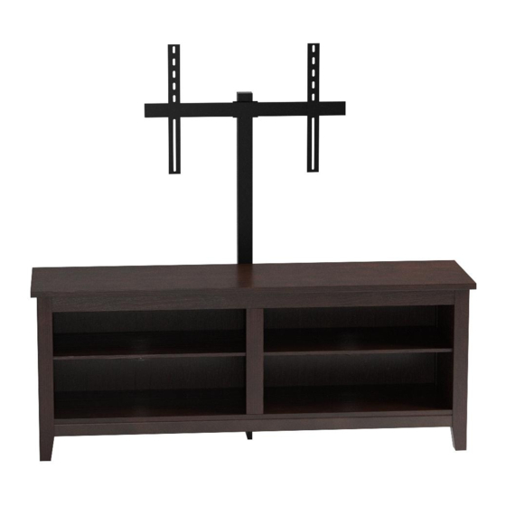
ITEM # : W58CSP-MT
Assembly Instructions
0
0
0
0
D
Revised 03/2017
0
0
0
0
D
P.1
Advertisement

Related Manuals for Walker Edison W58CSP-MT


Summary of Contents for Walker Edison W58CSP-MT
- Page 1 ITEM # : W58CSP-MT Assembly Instructions Please visit our website for the most current instructions, assembly tips, report damage, or request parts. www.walkeredison.com Revised 03/2017 Copyright © 2012, by Walker Edison Furniture Co., LLC. All rights reserved.
- Page 6 Insert dowels (A) into panel (2). Screw cam bolts (B) into panels (1,2). Insert dowels (A) into panel (4,15) and slats (6,7). Screw cam bolts (B) into slat (5).
- Page 7 Insert dowels (A) into legs (11,12,13,14) and panels (3). Screw cam bolts (B) into legs (11,12,13,14). Attach legs (11,13) to panel (3) using cam bolts and dowels as guides. Insert cam locks (C) into panel (3) and tighten with a screwdriver.
- Page 8 Attach legs (12,14) to second panel (3) using cam bolts and dowels as guides. Insert cam locks (C) into panel (3) and tighten with a screwdriver. Attach slat (7) to panel (2) using cam bolt and dowels as guides. Insert cam lock (C) into slat (7) and tighten with a screwdriver.
- Page 9 Attach support leg (8) to panel (2) using bolts (D). Tighten bolts (D) with wrench (H). Attach slat (5) to panel (4) using cam bolts and dowel as guides. Insert cam locks (C) into panel (4) and tighten with a screwdriver.
- Page 10 Attach panel (4,15) to panel (2) using bolts (D). Tighten bolts (D) with wrench (H). Attach slat (6) to slat (5) using dowel as guide.
- Page 11 Attach panel (3) with legs (11,13) to the assembly from the previous step using cam bolts and dowels as guides. Insert cam locks (C) into panel (2) and slat (6) and tighten with a screwdriver. Attach second panel (3) with legs (12,14) to the assembly from the previous step using cam bolts and dowels as guides.
- Page 12 Carefully slide panels (10) into place along the back of the assembly. Carefully attach panel (1) to the assembly using cam bolts and dowels as guides. Insert cam locks (C) into the assembly as shown above and tighten with a screwdriver.
- Page 13 Secure panels (10) with plastic wedges (E) and screws (F). Cover all visible cam locks with stickers (K) as desired.
- Page 14 Insert shelf support pins (G) into the assembly at desired shelf heights. Carefully place shelves (9) on shelf support pins (G). Completed stand assembly. The following steps show the assembly and attachment of the TV mount.
- Page 15 Attach lateral support bar (b) to upright support bar (a) using bolts (e) and washers (f). Attach support brackets (d) to upright support bar (a) using bolts (e) and washers (f). Slide mounting bars (c) onto lateral support bar (b). Secure mounting bars (c) by screwing adjustment knobs (g) into place.
- Page 16 Attach TV mount to stand assembly using bolts (e) and washers (f). Tighten bolts (e) with wrench (h).
Need help?
Do you have a question about the W58CSP-MT and is the answer not in the manual?
Questions and answers