
Related Manuals for Promax DT-800

Summary of Contents for Promax DT-800
- Page 1 DT-800 CONTROL MODULE Test Equipment Depot - 800.517.8431 - 99 Washington Street Melrose, MA 02176 TestEquipmentDepot.com DIGITAL TV HEADEND - 0 MI1787 -...
- Page 3 SAFETY NOTES Read the instruction manual before using the equipment, mainly "SAFETY RULES" paragraph. The symbol on the equipment means "SEE USER’S MANUAL". In this manual may also appear as a Caution or Warning symbol. Warning and Caution statements may appear in this manual to avoid injury hazard or damage to this product or other property.
-
Page 4: Table Of Contents
Instruccions for installation ................10 4. INSTRUCCIONES DE UTILIZACIÓN..............11 Description of the Controls and Elements ............11 Arrows and Function Keys Description ............. 12 LEDs Table......................13 DT-800 Starting Up ................... 13 Main Screen ...................... 14 PASSWORD ..................... 16 CONFIGURATION .................... 17 4.7.1 Description of the initial setup screen ............ - Page 5 CONTROL MODULE. DT-800...
-
Page 6: General
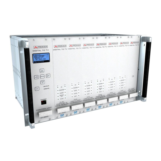
DT-800 is the control and power module, therefore is the most important module of the DTTV system. The DT-800 controls the DTTV headend, which would be made up to a maximum of seven modules. Two cable bus connect the control module to the other modules of the headend. - Page 7 Mains cord. 1 x CC043 Cable Alim. 3 mod. 1 x CC044 Cable Alim. 4 mod. 1 x 0 MI1787 Manual de Instructions DT-800. OPTION OP-800-P Power Option. Output voltage +12 V, 18 A max. +5 V, 14 A max.
-
Page 8: Safety Rules
CONTROL MODULE. DT-800 2. SAFETY RULES 2.1 General The safety could not be assured if the instructions for use are not closely followed. Use this equipment connected only to systems with their negative of measurement connected to ground potential or isolated from the network. -
Page 9: Descriptive Examples Of Over-Voltage Categories
CONTROL MODULE. DT-800 Symbols related with safety: 2.2 Descriptive Examples of Over-Voltage Categories Cat I Low voltage installations isolated from the mains. Cat II Portable domestic installations. Cat III Fixed domestic installations. Cat IV Industrial installations. Page 4 04-2012... -
Page 10: Installation
CONTROL MODULE. DT-800 3. INSTALLATION 3.1 DT-900 Sub-rack The DT-900 is a metallic casing (sub-rack), where the DTTV modules are installed (Fig. 1). Supplied accessories allow the subrack to be set up in two ways: Installing it in a 19 " rack cabinet (Fig. 2) or anchoring it on a wall. - Page 11 CONTROL MODULE. DT-800 Figure 2.- Assembling a DT-900 in a Rack Cabinet. Figure 3.- Tilting System. Page 6 04-2012...
-
Page 12: Instalación De Los Módulos En El Dt-900
3.3 Connecting wires The modular composition of the DTTV headend makes it flexible to adapt it to customer needs. The DT-800 control module is able to control up to 7 modules. 04-2012 Page 7... - Page 13 CC027 Figure 5.- Application example DTTV. The wiring must be done when the DT-800 module is off. You do not have to turn it on until ALL connecting work is done (on one hand control cables between the CPU and the modules and on the other hand, TS cables between modules). This is because during the starting up, the CPU scans all the modules, in order to determine the relation among them.
- Page 14 CC027 Figure 6.- Application example DTTV. The DT-800 has an electric current sensor that prevents it from starting up when it is not connected to any module. Therefore the control module will not be ON if at least one connection is made previously.
-
Page 15: Instruccions For Installation
CONTROL MODULE. DT-800 For an optimal use of the capabilities of the DTTV, it is advisable to use an universal LNB with independent outputs or an universal LNB with dual polarity (V/H) and dual band (L/H), both with a switchable splitter for satellite, in order to be able of distributing simultaneously signals in differents bands and polarisations. -
Page 16: Instrucciones De Utilización
CONTROL MODULE. DT-800 4. INSTRUCCIONES DE UTILIZACIÓN 4.1 Description of the Controls and Elements The only element of control is the DT-800 module. The rest of modules refer to their status by LEDs place on the front of the module. Frontal Panel Figure 7.- Front Panel DT-800. -
Page 17: Arrows And Function Keys Description
CONTROL MODULE. DT-800 [4] Ethernet RJ-45 Connector [5] Online LED [6] Error LED [7] Power Connector (IEC C14). [9] Power Switch [10] Power and Control Output 4.2 Arrows and Function Keys Description LINE ON ERROR Figure 8.- Function Keys. Enter the menu / Validate / Select / Deselect. -
Page 18: Leds Table
Transport Stream (too fast, TS wrong...). GREEN DVB-T output signal is correct. DVB-T Problem at the output. PROGRAM INTERMITTENT GREEN DT-800 is programming the unit. ASYNCHRONOUS DT-800 have received INTERMITTENT GREEN communication from the module for more than 60 seconds. -
Page 19: Main Screen
CONTROL MODULE. DT-800 After starting up, the DT-800 scans the modules connected to it in order to detect how many and what modules are and if there is any problem. During the scan, the control module carries out the assignment of bus addresses and after that an AUTOLINK, which consists in identifying those receivers / modulators paired (eg DT-301/302 with DT-101/102). - Page 20 CONTROL MODULE. DT-800 Figure 9.- Main Screen. The automatic position assignment does not have any practical effect. Each time you restart the DTTV, the control module will assign different positions to each module. If you do not like this way to assign, Then you can create and save your own assigment.
-
Page 21: Password
CONTROL MODULE. DT-800 If any of the modules is not listed or its status is not OK, check the connections, especially the control and power cord, which is what connects the control unit with the modules, and by which is transmitted the power supply and the identification data and settings. -
Page 22: Configuration
At the central area of the screen it appears the name of the module (Fig. 12.-), on the figure is the DT-800 control unit. Note that the system counts the double modules like two different units and the configurations of them are independent. -
Page 23: Browsing The Setup Menu
The first module that appears after entering the CONFIGURATION menu, is the control unit DT-800. The order of appearance of the rest of modules may vary depending on the location and connection of the modules at the rack and the automatic assigment made by the control unit when booting. -
Page 24: Entering, Editing And Selecting Values
CONTROL MODULE. DT-800 Figure 13.- 4.7.3 Entering, Editing and Selecting values Selecting values In case you want to SELECT a value among the available ones, use the arrows LEFT or RIGHT to move among them. When the screen displays the wanted value, press ENTER to confirm it and exit. - Page 25 On one hand you can save your settings using the SAVE option on each module. On the other hand you can save the settings of all modules at once using the SAVE ALL option, which is on the DT-800 menu. Page 20...
-
Page 26: Dt-800 Configuration
The DT-800 is the control and power module, and therefore is the most important module of the DTTV. The DT-800 controls the DTTV headend, which its compose by up to seven modules. Two wire-bus connect the control module to the remaining modules of the headend. - Page 27 CONTROL MODULE. DT-800 Figure 15.- Menu tree DT-800. Page 22 04-2012...
- Page 28 CONTROL MODULE. DT-800 4.7.4.2 Configuration options DT-800. The options of the menu CONFIGURATION at the module of control DT-800 are: Manual Assigment. If the Auto assigment done automatically by the system when starting does not match the actual location of the modules in the rack, this option allows you to change this assigment manually.
- Page 29 CONTROL MODULE. DT-800 4.- When finished press UP ONID Config NID Config (Network Identifier Configuration). NIT VERSION It is a private table about information of the Network This menu has two options: MODE and VERSION NUMBER. When MANUAL mode is selected...
-
Page 30: Pkupdate
4.- Click on the updating file and press "Open." 5.- Use the key "MODEL" in order the program detects the DT-800 module. If it does not comunícate then check the communication parameters by pressing the setup key . Check also the cable network is working properly. - Page 31 CONTROL MODULE. DT-800 8.- The program will update all units of the same type in the head end, that is, if the firmware affects units DT-30X, and there are more than one in the head end, they all will be updated.
-
Page 32: Practical Examples Of Systems Dttv
CONTROL MODULE. DT-800 5. PRACTICAL EXAMPLES OF SYSTEMS DTTV The owner of a hotel in Menorca, Mr. Ferrer, wants to give the hotel a touch of distinction over the competition, so he has decided to install flat TV screens with built in DTT tuner in each room and a satellite dish. - Page 33 CONTROL MODULE. DT-800 And the electrical connections scheme. Figure 19 .- 5.- Search data for the tuning of the channels and services. The tuning data for the channel where are the Italian services "Canale 50” and “TV7 Lombardia” are: Frequency: 11.541.
- Page 34 CONTROL MODULE. DT-800 Frequency: 11,604. Polarization: Horizontal. Symbol Rate: 22000. FEC: 5/6. Standard: DVB-S QPSK. 6.- After obtaining the data, the DT-302 dual module is configured in order to tune the channels selected. Turn on the and enter, step by step, all the settings.
- Page 35 CONTROL MODULE. DT-800 10.- Now it only rests to connect the resultant signal to the TV distribution network and tune all the TV sets with the new services. Figure 20.- After a few months, Mr. Ferrer is very pleased. German and Italian clients appreciate having channels in their own language at the hotel, and they feel more comfortable.
-
Page 36: Glossary Of Terms
CONTROL MODULE. DT-800 6. GLOSSARY OF TERMS MODULATOR: In telecommunications, the modulation is the process of varying a periodic waveform, i.e. a tone, in order to use that signal to convey a message. Normally a high-frequency sinusoid waveform is used as carrier signal. - Page 37 CONTROL MODULE. DT-800 COFDM: Coded Orthogonal Frequency Division Multiplexing modulation system used in the radio and televisión systems. Unlike other systems that modulate in a single carrier frequency with a very high rate of symbols, COFDM modulates information in many carrier frequencies, where each one has a very low rate of symbols.
- Page 38 CONTROL MODULE. DT-800 MER: It is the Modulation Error Rate. It is a measure that allows knowing how good a modulated digital signal is. It is the equivalent of the information provided by the signal/noise rate in the analog modulations.
- Page 39 CONTROL MODULE. DT-800 FIRMWARE: Firmware is a term sometimes used to denote the fixed, usually rather small, programs that internally control various electronic devices. Typical examples range from end user products such as remote controls or calculators, via computer parts and devices like harddisks, keyboards, TFT screens or memory cards, all the way to scientific instrumentation and industrial robotics.
-
Page 40: Maintenance
CONTROL MODULE. DT-800 7. MAINTENANCE 7.1 Cleaning Recommendations CAUTION To clean the cover, take care the instrument is disconnected. CAUTION Do not use scented hydrocarbons or chlorized solvents. Such products may attack the plastics used in the construction of the cover. - Page 41 PROMAX ELECTRONICA, S. L.
Need help?
Do you have a question about the DT-800 and is the answer not in the manual?
Questions and answers