Advertisement
Monitoring Relays
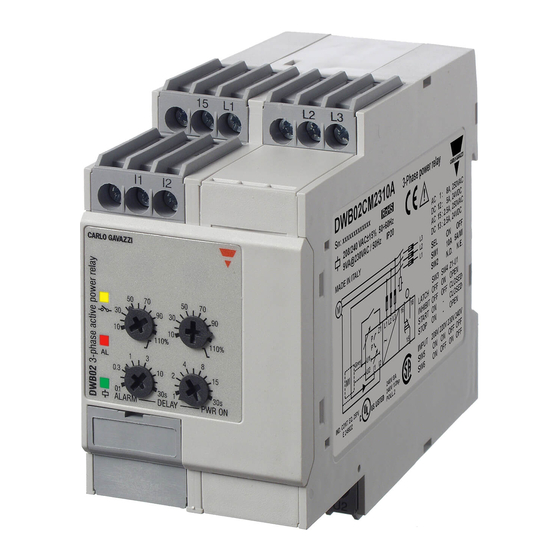
3-Phase Active power
Types DWB02, PWB02
DWB02
Product Description
DWB02 and PWB02 are
precise TRMS active power
monitoring
relays
for
phase balanced systems.
They can be used for moni-
toring the actual load of
asynchronous motors and
other symmetrical loads, as
well as the power consump-
tion by of system.
Start/stop input allows to
use a manual switch to start
and stop the system, with-
out the need of an auxiliary
Type Selection
Mounting
Output
DIN-rail
SPDT
Plug-in
SPDT
Input Specifications
Input
Voltage (Own power supply):
3 - phase
DWB02:
PWB02:
M23:
DWB02CM48:
PWB02CM48:
DWB02CM69:
1- phase
DWB02CM23:
PWB02CM23:
Current:
DWB02:
PWB02:
Measuring ranges
Active power
Direct input:
Specifications are subject to change without notice (16.10.08)
PWB02
device.
The advantage of using the
3-
latch function is that the
alarm status can be kept
even after the end of the
alarm condition. Inhibit func-
tion can be used to avoid
relay operation when not
desired (maintenance, tran-
sitions).
The LED's indicate the state
of the alarm and the output
relay.
Supply:
208 to 240 VAC
DWB 02 C M23 10A
PWB 02 C M23 10A
L1, L2, L3
5, 6, 7
208 to 240 VAC ± 15%
380 to 480 VAC ± 15%
380 to 415 VAC ± 15%
600 to 690 VAC ± 15%
L1, L2
5, 6
208 to 240 VAC ± 15%
5A, 10A: I1, I2
MI...:U1, U2
5A, 10A: 11, 10
MI...: 9, 8
Upper level Lower level
10 to 110 % 10 to 110 %
AACrms
Max. curr.
(30s)
0.5 to 5A
30A
1 to 10A
50A
• TRMS active power relays for three phase
balanced applications
• Measuring if active power is within set limits
• Measuring voltage on own power supply
• Measuring ranges: 5A, 10A, MI current transformers
• Power ON delay 1 to 30 s knob selectable
• Separately adjustable upper/lower level on relative
scale
• Programmable latching or inhibit at set level
• Automatic and manual start and stop of the system
• Output: 8 A SPDT relay N.D. or N.E. selectable
• For mounting on DIN-rail in accordance with DIN/EN
50 022 (DWB02) or plug-in module (PWB02)
• 45 mm Euronorm housing (DWB02) or 36 mm plug-in
module (PWB02)
• LED indication for relay, alarm and power supply ON
Ordering key
Housing
Function
Type
Item number
Output
Power Supply
Range
Supply:
Supply:
380 to 415 VAC
380 to 480 VAC
DWB 02 C M48 10A
PWB 02 C M48 10A
Standard CT (examples)
TADK2 50 A/5 A
CTD1 150 A/5 A
CTD4 400 A/5 A
TAD12 1000 A/5 A
TACO200 6000 A/5 A
MI CT ranges
MI 100
MI 500
Note:
The input voltage cannot
raise over 300 VAC with
respect to ground (PWB02
only)
Contact input
DWB02
PWB02
Disabled
Enabled
Pulse width
Hysteresis
DWB 02 C M48 10A
Supply:
600 to 690 VAC
DWB02 C M69 10A
5 to 50 A
60 A
15 to 150 A
180 A
40 to 400 A
480 A
100 to 1000 A
1200 A
600 to 6000 A
7200 A
10 to 100 A
250 AAC
50 to 500 A
750 AAC
Terminals Z1, U2
Terminals 2, 9
> 10 kΩ
< 500 Ω
> 500 ms
~ 2% of set value - fixed
1
Advertisement
Table of Contents

Subscribe to Our Youtube Channel
Related Manuals for CARLO GAVAZZI DWB02


Summary of Contents for CARLO GAVAZZI DWB02
- Page 1 • For mounting on DIN-rail in accordance with DIN/EN 50 022 (DWB02) or plug-in module (PWB02) DWB02 PWB02 • 45 mm Euronorm housing (DWB02) or 36 mm plug-in module (PWB02) • LED indication for relay, alarm and power supply ON Product Description...
-
Page 2: Output Specifications
Start/stop mode, relay NE. phase balanced system. The drops below the lower set- flashing, and the output In this application DWB02 or relay has an adjustable pow- point or raises above the relay releases after the set PWB02 are directly connect-... - Page 3 3-phase power to command a contactor in supply to the terminals L1, series to the load (see last L2 and L3 (DWB02) - 5, 6 two wiring diagrams). and 7 (PWB02) taking care of the sequence. Function/Range/Level/Time Setting...
-
Page 4: Operation Diagrams
Start/Stop contact (Closed = Start; Open = Stop) Upper level Hysteresis Hysteresis Lower level Active power Power Relay ON Wiring Diagrams DWB02 - Direct connection PWB02 - Direct connection Latch/Inhibit Latch/Inhibit Contact Contact Specifications are subject to change without notice (16.10.08) - Page 5 It is possible for both 3-phases loads and of 1-phase loads, either through direct connection or external cur- rent metering transformer. DWB02 - Direct connection - Manual start and stop (NE relay) PWB02 - Direct connection - Manual start and stop (NE relay)
- Page 6 DWB02, PWB02 Dimensions DIN-rail Plug-in 99.5 28.5 28.5 Specifications are subject to change without notice (16.10.08)
Need help?
Do you have a question about the DWB02 and is the answer not in the manual?
Questions and answers