Table of Contents

Related Manuals for Viessmann Cascade control unit


Summary of Contents for Viessmann Cascade control unit
- Page 1 Installation, operating and service instructions for heating engineers Cascade control unit Weather-compensated cascade control for up to four gas fired wall-mounted boilers Cascade control unit Please keep safe 5862 474 GB 3/2003...
-
Page 2: General Information
¨ This symbol denotes important information which must be observed to prevent material losses. Product information Cascade control unit, part no. 7170 857, weather-compensated cascade control for multi-boiler systems with up to four gas fired wall-mounted boilers and one distribution pump. -
Page 3: Table Of Contents
Contents Index Page General information Safety instructions ........................Product information . -
Page 4: Installation And Connections
Installation and connections Installation conditions H Install the control unit at eye level H Max. ambient temperature and as close to the connected see "Specification". system components as possible. H Do not install the control unit near water sprays. Control unit installation 1. -
Page 5: Electrical Connections
C Distribution pump positions and connect in accordance D Fault message (zero volt) with the diagram. E Separator (as delivered condition) F Viessmann 2 wire BUS for External switching contacts connection to Vitotronic 050, Connect the external switching Vitotronic 050 accessory... - Page 6 Mains electrical connection If the outside temperature for Connect the supplied mains cable in Vitotronic 050 is to be adopted from accordance with the diagram (see the cascade control unit, set code page 5). "97:1". Distribution pump Connect acc. to diagram (see page 5).
-
Page 7: Relieving Cable Strain
Installation and connections Relieving cable strain 1. Fit a strain relief (supplied) to all 2. Fit the cover to the termination cables. chamber. -
Page 8: Control
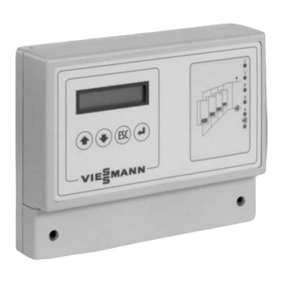
Control Operating controls and indicators A Display C System diagram B Push buttons D Function displays... - Page 9 Control Operating controls and indicators (cont.) Push buttons Subject to configuration and operating level, keys can be used to display and/or amend the various details in the main and sub-menus. The key function is subject to the respective menu item that is displayed when the key is pressed.
-
Page 10: Operating Level Selection
Control Operating level selection The control unit has three operating levels. Operating level 1 Display of simple parameters, such as operating mode and software version. Operating level 2 Display of the most important operating details (e.g. actual and set flow temperature, switching periods and settings, such as set room temperature, set flow temperature) and modification of set values. -
Page 11: Initial Start-Up/Configuration
Control Initial start-up/configuration The control unit covers two setting ranges, which must be configured separately: H General control unit (described in the menu as "Control unit 001 A") for general details, such as date and time H Multi-boiler control unit (described in the menu as "Control unit 001 B") for the control of multi-boiler systems, where boilers are enabled subject to temperature. - Page 12 Control Initial start-up/configuration (cont.) Multi-boiler control unit Preconditions: Operating level 3 must be selected (see page 10). Select "Multi-boiler control unit" with , if Control unit 001 B "Multi-boiler control unit" is not already multi-boiler system displayed; confirm with Select "Configuration" with ;...
- Page 13 Control Initial start-up/configuration (cont.) Pump Select "Yes" if a distribution pump is to be Pump connected to the control unit. Number of boilers Enter the number of boilers in the multi-boiler Number of boilers system. Flue gas cascade Select "Yes" if a pressure flue gas cascade is Flue gas cascade installed.
-
Page 14: General Details (General Control Units)
Control General details Activating operating level 3 (see page 10). to confirm Relay test Operating level confirm; Please note: display pump If in the following you wish to display flashes jump to the next menu item, for selecting relay continue with back to previous menu Operating details Configuration... -
Page 15: System Details (Multi-Boiler Control Unit)
H Standby mode H Fault H Automatic summer mode H External demand H Heat demand via Viessmann 2 wire BUS H Frost protection H Set flow temperature H Set room temperature H Outside temperature H Boilers 1 to 4... - Page 16 Control System details (cont.) Set values Time switch confirm confirm for selecting following for selecting weekday parameters: confirm; switching time flashes H Set room temperature change time Standard/reduced mode/ confirm holiday mode back to previous menu H Outside temp. low end H Flow temp.
-
Page 17: Functions
Functions Operating conditions You can scan the operating conditions from the "Operating details" menu in the "Multi-boiler control unit" function area (see page 15). The following operating conditions may apply: H Standard mode (standard room temperature, e.g. day) H Reduced mode (reduced room temperature, e.g. night) H Holiday mode (reduced room temperature, e.g. - Page 18 Functions Operating conditions (cont.) Time switch Preconditions: "Time switch Yes" must be configured (see page 12). In the time switch program, two different switching periods can be set for each weekday. Each switching period requires the input of a switch-on and a switch-off point. Within the switching period, the control unit operates in standard mode;...
- Page 19 Functions Operating conditions (cont.) Party mode A switching contact at the party key input enables the control unit to be changed over to standard mode. The control unit will operate in standard mode as long as the switching contact is closed. Set value (multi-boiler control unit) The impulse at the party key input lets the Party key...
- Page 20 Functions Operating conditions (cont.) Start-up optimisation (early heat-up) The start-up optimisation ensures that the boiler is heated up before the standard mode commences, subject to room and outside temperature. This ensures that the set room temperature is achieved before the standard mode commences.
- Page 21 Functions Operating conditions (cont.) Summer mode The function activates if the adjusted outside temperature is higher than the set room temperature in standard mode plus the set "Difference summer mode"; central heating remains OFF . You can adjust the period during which the average outside temperature is calculated.
-
Page 22: Set Room Temperature
Functions Operating conditions (cont.) Shutdown during reduced and holiday mode This function ensures that the system is shut down after the change from standard to reduced or holiday mode, to ensure that the reduced set room temperature is achieved. Operating details (multi-boiler control unit) Because of the set values, the set flow Flow 30ºC... -
Page 23: Set Flow Temperature
Functions Set flow temperature Weather-compensated flow temperature acc. to heating curve The adjustment of the heating curve is subject to the system design and the climatic zone. Adjust the following heating curve values: H Low end outside temperature/flow temperature H Design value outside temperature/flow temperature H Heating curve slope (subject to the type of heating surfaces) Outside temperature in °C... - Page 24 Functions Set flow temperature (cont.) Set values (multi-boiler control unit) In most cases, this value represents the set room Outside temp. temperature in standard mode. low end 20ºC Generally with radiator systems, this value Flow temp. corresponds to the low end temperature. low end 20ºC A higher setting is recommended for convector...
- Page 25 (actual flow temperature, set flow temperature). In the "Operating details" menu (see page 15) you can scan whether the control unit is set to "External demand/heat demand via Viessmann 2-wire BUS". Operating details (multi-boiler control unit) Heat demand from Vitotronic 050.
-
Page 26: Multi-Boiler Control Unit
Functions Multi-boiler control unit The modulating cascade control communicates with the boilers via the KM BUS interface. It calculates the required flow temperature using a weather-compensated control unit. Starting up and shutting down individual boilers Depending on heat demand, individual boilers are started up or shut down. A boiler will be started up if: H the required heat load is higher than the total output of all currently operational boilers... - Page 27 Functions Multi-boiler control unit (cont.) Start-up delay A delay before start-up of individual boilers can be selected, for example to prevent boilers from cycling. A Boiler base load 1 FK Lag boiler B Mod. to boiler 1 K 1 Boiler 1 C Lag boiler base load System output D Mod.
-
Page 28: Distributor Pump
Functions Multi-boiler control unit (cont.) Automatic change of the start-up sequence Preconditions: "Boiler sequence change Yes" must be configured (see page 13). Once a week, the control unit changes the sequence in which the boilers are started and shut down, subject to the number of hours run by each boiler. The boiler which has run the fewest hours is the first to be started, followed by the boiler with the second lowest number of hours run, etc. -
Page 29: Safety And Monitoring Equipment
Functions Safety and monitoring equipment Function monitoring by detecting the flow temperature The heating system function is monitored by comparing the required and the actual flow temperature. A fault message is displayed if, within an adjustable period, the flow temperature does not reach the required value less the adjustable tolerated temperature deviation. - Page 30 Functions Safety and monitoring equipment (cont.) Pump protection control Preconditions: "Pump protection Yes" must be configured (see page 13). Daily between 12:00 and 12:05 hrs., the pump will be started to prevent it from seizing up. Hours run and start-up counter The hours run and start-up counters store the number of hours run and the number of start-ups of the boilers and distributor pumps (if installed), which are regulated by the control unit.
- Page 31 Functions Safety and monitoring equipment (cont.) Fault messages In the event of a fault recognised by the control unit (e.g. faulty sensor), the status display will show "Status display fault", and the fault indicator "U" illuminates. The "Fault" menu has the following functions: H List of all current faults H Date and time of last change in fault situation H List of the last 10 faults...
-
Page 32: Troubleshooting General Faults
Troubleshooting General faults Connected system components are not correctly controlled or not controlled at all H Check connections and cables (see installation) H Check the voltage at the terminals H Scan operating conditions in the "Operating details" menu Room temperature too cold/too warm H Check set values H Check actual room temperature H Check boiler control units of connected boilers... -
Page 33: Faults Indicated In The "Faults" Menu
Troubleshooting Faults indicated in the "Faults" menu Cause: Flow temperature sensor Flow temp. not/incorrectly connected or faulty Result: Functions based on the flow temperature are failing Remedy: Check the connections and the sensor using the resistance table (see page 34) Cause: The flow temperature does not reach System too slow... -
Page 34: Sensor Resistance Table
Troubleshooting Faults indicated in the "Faults" menu (cont.) Cause: The room temperature is too low to Frost prot. room ensure frost protection Result: The control unit creates a heat demand Remedy: Check system components Cause: At least one boiler is in a fault state Boiler (multi-boiler control unit) error code:... -
Page 35: Parts List
Quote the part no. and the item no. of the required part (as per this parts list). Obtain common parts from your local supplier. Parts 001 Cascade control unit complete 002 Outside temperature sensor 003 Flow temperature sensor 006 Mains cable 008 Connection cable 2 wire BUS... -
Page 36: Specification
Contact your local heating contractor if you have any questions regarding the maintenance and repair of your heating system. You may, for example, find local heating contractors on the internet under www.viessmann.de. Viessmann Limited Viessmann Werke GmbH & Co Hortonwood 30, Telford D 35107 Allendorf Shropshire, TF1 7YP , GB Tel:...
Need help?
Do you have a question about the Cascade control unit and is the answer not in the manual?
Questions and answers