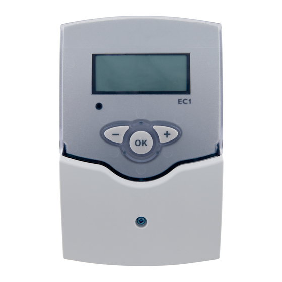
Viessmann VITOSOLIC 100 Installation And Service Instructions Manual
Electronic temperature differential control unit for solar heating system
Hide thumbs
Also See for VITOSOLIC 100:
- Installation and service instructions manual (72 pages) ,
- Installation and service instructions for contractors (36 pages) ,
- Operating instructions for the system user (13 pages)
Summary of Contents for Viessmann VITOSOLIC 100
- Page 1 Vitosolic 100 See Applicability on the last page. VITOSOLIC 100 Please keep safe...
-
Page 2: Safety Instructions
Safety instructions Please follow these safety instructions closely to prevent accidents and material losses. Safety regulations Repair work Initial start-up Instructing the system user Earthing/lightning protection of the solar heating system ¨ Safety instructions In this instruction manual, this heading denotes information which must be observed to prevent accidents and material losses. - Page 3 Index System design Installation and connections Initial start-up Service scans Troubleshooting System details/functions Parts list Appendix Keyword index Applicability...
-
Page 4: System Design
System design Dual mode DHW heating with Vitocell B 100 or Vitocell B 300 DHW heating without solar energy º Safety instructions With temperatures higher than 60 ºC, DHW with solar energy limit the DHW temperature to 60 ºC by installing a mixing device, e.g. a thermostatic mixing valve (DHW cylinder accessory). - Page 5 System design High limit safety cut-out, see page 8.
- Page 6 System design Item Description Number Part no. Control of DHW cylinder loading by solar energy Control of DHW cylinder loading by boiler Use a threaded elbow (standard delivery for Vitocell B 100, accessory for Vitocell B 300). Vitocell B 100: observe the max. connectable absorber surface area. Vitocell B 300: Use a cylinder cap (DHW cylinder accessory).
- Page 7 Control unit installation Installation location Electrical connections...
-
Page 8: Solar Circuit Pump
Solar circuit pump Installation Connection The "Solar Divicon" pump station includes the circulation pump with connecting cable. Alternative pumps must be type-tested and fitted in accordance with manufacturer's instructions. High limit safety cut-out Installation Connection Separate installation instructions Temperature setting º... - Page 9 Sensors Collector temperature sensor Installation Connection Collector installation instructions Cylinder temperature sensor Installation Connection DHW cylinder installation instructions...
-
Page 10: Mains Electrical Connection
Mains electrical connection Regulations ¨ Safety instructions Do not interchange cores. L: Terminal 20 N: Terminal 19... - Page 11 Steps º Further details regarding individual steps Commissioning the control unit...
-
Page 12: Adjusting System Settings
Further details regarding individual steps Adjusting system settings Temperatures Functions ¨ Observe the max. permissible DHW temperature. Further parameters Calling up the setting level Please note: After approx. 2 minutes, the display reverts to the standard screen (showing the collector and DHW cylinder temperature) if no confirmation of modified values is received or other settings are... - Page 13 Further details regarding individual steps Relay test...
-
Page 14: Software Version
Temperatures Heat volume Circulation pump hours run Software version Please note: For an explanation to the display symbols, see the operating instructions. - Page 15 Fault messages...
-
Page 16: Checking Sensors
Checking sensors Temperature Resistance º º Specification º º º... - Page 17 Changing the fuse...
- Page 18 Summary Setting Setting Explanation range DT control unit Please note: DO can be set to a min. of 0.5 K above DF , DF a maximum of 0.5 K below DO. These functions only operate in conjunction with relay 2. Only in conjunction with connection extension.
- Page 19 Summary Setting Setting Explanation range º FN = 1 º º º º CN = 10 ºC º º...
- Page 20 Summary Setting Setting Explanation range Vitosol service instructions...
-
Page 21: Special Functions
Special functions Maximum cylinder limit SF = 1 Suppression of reloading by boiler SF = 2 Systems with Vitotronic and Systems with additional Viessmann Calotronic control units with KM control units º below... - Page 22 Special functions Remove jumper when making this connection. Connection, see page 23.
- Page 23 Special functions Connecting cable, part no. 7450 061, required.
- Page 24 Special functions Additional function for DHW heating SF = 3 º Thermostat function SF = 4 º º º...
- Page 25 Maximum cylinder temperature control FN = 1 Collector cooling function FN = 3 º...
- Page 26 Reverse cooling function FN = 2 º...
-
Page 27: Parts List
Parts list When ordering spare parts Parts... -
Page 28: Specification
Specification º º... -
Page 29: Declaration Of Conformity
Declaration of conformity Vitosolic 100 conforms to the following standards: This product is identified in accordance with the following guidelines: as follows:... - Page 30 Keyword index...
- Page 31 Keyword index...
- Page 32 Applicability...


Need help?
Do you have a question about the VITOSOLIC 100 and is the answer not in the manual?
Questions and answers