Table of Contents
Advertisement
Available languages
Available languages
Quick Links
Advertisement
Table of Contents

Related Manuals for Atlantis Upower A03-OP1001


Summary of Contents for Atlantis Upower A03-OP1001
- Page 2 ITALIANO Questo prodotto è coperto da garanzia Atlantis On-Site della durata di 2 anni. Per maggiori dettagli in merito o per accedere alla documentazione completa in Italiano fare riferimento al sito www.atlantis-land.com. ENGLISH This product is covered by Atlantis On-Site 2 years warranty. For more detailed informations please refer to the web site www.atlantis-land.com.
-
Page 3: Table Of Contents
ITALIANO Manuale d’Uso ....................11 1.0 INTRODUZIONE AL PRODOTTO .............. 11 1.1 Verifica Iniziale ..................11 1.2 Contenuto della confezione..............11 2.0 INSTALLAZIONE e CONFIGURAZIONE ............. 13 2.1 Verifiche Iniziali ..................13 2.2 Pannello Posteriore ................14 2.3 Setup dell’UPS ..................15 3.0 UTILIZZO DELL’UPS ................ - Page 4 3.5 Audible Alarm ..................45 3.6 Faults Reference Code ................45 3.7 Warning indicator .................. 45 APPENDIX A: TROUBLE SHOOTING & SUPPORT ..........47 A.1.1 UPS ..................47 A.1.2 Battery ..................48 A.1.3 ViewPower ..................48 A.1.4 Operation/Storage ................49 A.1.5 Support ..................
- Page 5 Atlantis. Tutti i nomi di produttori e dei prodotti e qualsiasi marchio, registrato o meno, menzionati in questo manuale sono usati al solo scopo identificativo e rimangono proprietà...
- Page 6 Attenzione: Non rimuovere i pannelli esterni al fine di evitare il rischio di shock elettrico. Per ogni dubbio o perplessità rivolgersi a personale qualificato. Attenzione: Atlantis non è responsabile di danni causati a prodotti terzi imputabili all’utilizzo, all’installazione in ambienti non ignifughi o non idonei, alla rottura o al malfunzionamento di prodotti Atlantis.
- Page 7 Al fine di evitare rischi di incendi o shock elettrici, disporre l’apparato in ambiente indoor con temperatura ed umidità controllate e privo di agenti conduttori di ogni genere. Non installare in luoghi in cui il dispositivo sia sotto irraggiamento solare diretto. Non bloccare/ostruire per alcuna ragione le bocche di ventilazione/ventole poste nel pannello posteriore e assicurarsi che queste distino almeno 15cm dalla superficie più...
- Page 8 Restrizioni di responsabilità Il software di controllo, ove presente, è dato in licenza. Atlantis non offrirà supporto sull’utilizzo né potrà essere ritenuta responsabile per malfunzionamenti e/o perdita di dati da questo generati. Il software è stato testato solo in ambiente Windows (alcun supporto per Linux/MAC OS X verrà...
- Page 9 Atlantis, in qualità di produttore di questa apparecchiatura, è impegnato nel finanziamento e nella gestione di attività di trattamento e recupero dei rifiuti di apparecchiature elettriche ed elettroniche compatibili con l'ambiente e con la salute umana.
- Page 10 2014/30/UE e 2014/35/UE tramite l’utilizzo delle norme pubblicate nella gazzetta ufficiale della comunità Europea: Basso Voltaggio: EN 620040-1-1:2008+A1:2013 Compatibilità Elettromagnetica: EN 62040-2:2006 +AC:2006, EN 6100-3- 2:2014 La dichiarazione di conformità è disponibile on-line al link: ftp://ftp.hellatron.it (username: atlantis-dec@hellatron e pwd: atlantis).
-
Page 11: Manuale D'uso
Manuale d’Uso La ringraziamo per aver scelto un apparato Atlantis. Si raccomanda la lettura completa di questo manuale prima di utilizzare il prodotto. 1.0 INTRODUZIONE AL PRODOTTO Seguire attentamente tutte le istruzioni durante l’installazione. Leggere attentamente l’intero manuale prima di iniziare l’installazione del dispositivo. - Page 12 Non deve essere esposto direttamente ai raggi solari Deve essere collocato in ambienti con umidità controllata. E’ opportuno lasciare almeno 15 cm dalle feritoie al fine di consentire un’opportuna areazione. Non va collocato in ambienti infiammabili (va messo ...
-
Page 13: Installazione E Configurazione
2.0 INSTALLAZIONE e CONFIGURAZIONE Prima di iniziare l’installazione è opportuno effettuare un’ispezione del dispositivo. Controllare che tutti gli accessori siano presenti e nulla risulti danneggiato. Conservare l’imballo per usi futuri. 2.1 Verifiche Iniziali E’ opportuno verificare, prima di connettere i carichi all’UPS, che la massa ed il neutro di questi non siano cortocircuitate. -
Page 14: Pannello Posteriore
2.2 Pannello Posteriore Identificativo Utilizzo Connettere alla rete elettrica di alimentazione tramite il cavo fornito. Input circuit breaker. Circuito di protezione in ingresso. Il modello base include una scheda di comunicazione con... -
Page 15: Setup Dell'ups
interfaccia USB. Porta di comunicazione RS232. Slot per la connessione della scheda SNMP (opzionale). Non disponibile a partire dalla revisione 1.2. 4 Uscite (IEC 320): connettere i carichi ritenuti critici. Nel modello A03-OP1001(V1.2) sono presenti 3 uscite IEC. Ouput Terminal (contatti di uscita) solo nel modello A03- OP3451. - Page 16 USB Port RS232 Port Tramite il software di gestione (scaricabile all’indirizzo www.atlantis-land.com) è possible controllare lo stato di funzionamento dell’UPS e permettere lo spegnimento controllato del PC collegato tramite RS232/USB. Una sola interfaccia alla volta è attiva (o la USB o la RS232).
-
Page 17: Utilizzo Dell'ups
3.0 UTILIZZO DELL’UPS Nelle sezioni seguenti verrà illustrato come configurare e utilizzare propriamente il dispositivo. 3.1 Bottoni Frontali di Selezione Bottone Funzione Accensione dell’UPS: Premere per circa 2 secondi il bottone ON/Mute per accendere il dispositivo. Disattivazione allarme acustico: Quando l’UPS va in modalità... -
Page 18: Panello Led
scelta quando l’UPS trova modalità configurazione (Setting mode). Cambio messaggio visualizzatro sui LED: Premere questo bottone (per un paio di secondi) per cambiare l’informazione visualizzata sui LED. Una segnalazione acustica avviserà del cambiamento avvenuto. Una pausa di 10 secondi produce l’uscita da questa modalità. SELECT ... - Page 19 Display Funzione Messaggi di Allerta e Malfunzionamento (Fault Information) Indica la presenza di un messaggio di allerta o malfunzionamento nel dispositivo. Viene indicato il codice che ha generato l’errore/allerta/malfunzionamento. Consultare la sezione 3.7 per avere dettagli ulteriori. Informazioni sul Carico e Batterie Indica il livello di Carico (quando in modalità...
-
Page 20: Ups Setting
L’inverter è attivo. 3-3. UPS Setting LED6 LED7 LED8 LED9 LED10 LED1 LED2 LED3 LED4 LED5 Premere il bottone Select per 5 secondi, quando l’UPS è in modalità Bypass o StandBy, per entrare in modalità selezione. Adesso con i tasti ON/Mute e Select è possibile muoversi tra i menù... - Page 21 LED3 Lampeggiante: Impostazione Voltaggio in Uscita Interfaccia Settaggio E’ possibile scegliere uno tra i seguenti voltaggi in uscita. LED7: il voltaggio in uscita è 208Vac LED8: il voltaggio in uscita è 220Vac LED9: il voltaggio in uscita è 230Vac LED10: il voltaggio in uscita è 240Vac LED4 Lampeggiante: Attivazione/Disattivazione ByPass quando l’UPS è...
-
Page 22: Modalità Operative
3-4. Modalità Operative Modalità Descrizione Operativa Quando il voltaggio in ingresso è ONLINE nella finestra consentita, dispositivo provvede a fornire l’uscita secondo i valori impostati e alla ricarica delle batterie. Conversione Quando la frequenza di ingressoè frequenza compresa tra i 40Hz ed i 70Hz, l’UPS permette di ricostruire una frequenza in uscita di 50/60Hz a seconda delle impostazioni. -
Page 23: Allarmi Acustici
Standby L’UPS è spento e nessun carico connesso è alimentato, ma se collegato alla rete elettrica l’UPS può comunque caricare, necessario, le batterie. Scollegare il cavo di connessione alla rete elettrica ed aspettare che il Display sia spento. Alla riaccensione il dispositivo utilizzerà la configurazione appena impostatata. -
Page 24: Indicatori Di Allarmi
Boost anomalo LED5,10 Voltaggio elevato nel Caricatore LED5,7,8,9,10 Voltaggio basso nel Caricatore LED5,8,9,10 Temperatura LED5,7,8 3.7 Indicatori di Allarmi Condizione Suono Cablaggio di ingresso non Ogni secondo LED1,5 connesso correttamente Batteria non connessa LED2,5 Ogni secondo Batteria guasta LED5,9 Ogni secondo Batteria sovraccarica LED5,7,8,9,10 Ogni secondo... -
Page 25: Appendice A: Risoluzione Dei Problemi E Supporto
LED5,7,8,9 sono accesi Il voltaggio delle batterie è Chiamare l’assistenza mentre viene riprodotta troppo alto oppure tecnica di Atlantis. segnalazione caricatore è guasto. acustica continua. LED5,8,9,10 sono accesi Il voltaggio delle batterie è Chiamare l’assistenza mentre viene riprodotta troppo... -
Page 26: Batterie
Si raccomanda di sostituire le batterie una volta all’anno. Dove posso trovare 1. In un qualunque negozio specializzato. le batterie per la 2. Chiederle direttamente all’assistenza tecnica di Atlantis: sostituzione? 2 x 12VDC- 9A/h nell’A03-OP1001 4 x 12VDC- 9A/h nell’A03-OP2301... -
Page 27: Problematiche Del Software Viewpower
USB in dotazione. Il PC provvederà al rilevamento del dotazione? dispositivo ed alla sua corretta installazione. A questo punto scaricare dal sito (www.atlantis-land.com) il software di gestione. Software 1. Verificare che il cavo sia correttamente connesso. gestione non rileva 2. -
Page 28: Conservazione
A.1.6 Supporto Offerto Per qualunque altro problema o dubbio sul funzionamento del prodotto, è possibile contattare il servizio di assistenza tecnica Atlantis tramite l’apertura di un ticket on- line sul portale http://www.atlantis-land.com/ita/supporto.php. Nel caso non fosse possibile l’accesso al portale di supporto, è altresì possibile richiedere assistenza telefonica al numero 02/ 78.62.64.37 (consultare il sito per... -
Page 29: Appendice B: Cambio Delle Batterie
APPENDICE B: Cambio delle Batterie Prima di iniziare è opportune considerare questa come un’operazione delicata che va fatta da personale specializzato. Seguire tutte le precauzione seguenti: Nell’UPS è installata una batteria di accumulatori che è fonte di energia, per cui all’interno del gruppo vi sono delle tensioni pericolose presenti anche a gruppo spento e/o scollegato dalle rete elettrica. - Page 30 Copyright The Atlantis logo is a registered trademark of Atlantis. All other names mentioned mat be trademarks or registered trademarks of their respective owners. Subject to change without notice. No liability for technical errors and/or omissions. CE Mark Warning In a domestic environment, this product may cause radio interference, in which case the user may be required to take adequate measures.
- Page 31 Preparation Condensation may occur if the UPS system is moved directly from cold to warm environment. The UPS system must be absolutely dry before being installed. Please allow at least four (5) hours for the UPS system to acclimate the environment. Do not install the UPS system near water or in moist environments.
- Page 32 Hereby, Hellatron SrL, declares that this device is in compliance with the essential requirements and other relevant provisions of Directive 2014/30/EU and 2014/35/EU and: LVD: EN 620040-1-1:2008+A1:2013 EMC: EN 62040-2:2006 +AC:2006, EN 6100-3-2:2014 The declaration of conformity is available on-line to the following link: ftp://ftp.hellatron.it (username: atlantis-dec@hellatron pwd: atlantis)
- Page 33 PS.: The above mentioned information are reported herewith in compliance with Directive 2002/96/CE, which requires a separate collection system and specific treatment and disposal procedures for the waste of electric and electronic equipments (WEEE). For further and more detailed information, we invite you to visit our website at www.atlantis-land.com...
-
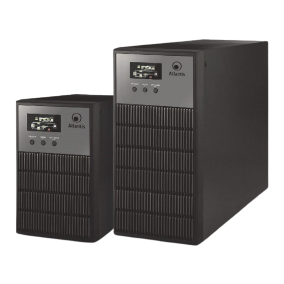
Page 34: Manual
MANUAL Congratulations on your purchase of Atlantis OnLine Double Conversion Tower UPS. This manual discusses how to install and use this device. 1.0 UPS This manual contains important safety instructions. Please follow all instructions carefully during installation. Read this manual thoroughly before attempting to unpack, install or operate. -
Page 35: Installation And Setup
To eliminate any overheating of the UPS, keep all ventilation openings free from obstruction and do not place any foreign objects on top of the UPS. Keep the UPS 15 cm away from the wall. 2.0 INSTALLATION and SETUP Before installation, please inspect the unit. -
Page 36: Rear Panel Explanation
Never connect neutral line of input to neutral line of output. Otherwise, it will cause the damage of the UPS. 2.2 Rear Panel Explanation Number Explanations AC input. Input circuit breaker. -
Page 37: Setup The Ups
USB communication port. RS232 communication port. Output receptacles: connect to mission-critical loads Output Terminal Block (only on A03-3451). For socket-type outputs, simply connect devices to the outlets. For terminal-type input or outputs, please follow below steps for the wiring configuration: Remove the small cover of the terminal block Suggest using AWG14 or 2.1mm2 power cords for 3KVA. - Page 38 For optimal computer system protection, install UPS monitoring software to fully configure UPS shutdown. Please follow steps below to download and install monitoring software: Download and install software from www.atlantis-land.com. See software document for installation instruction. When your computer restarts, the monitoring software will appear as an orange plug icon ( ) located in the system tray, near the clock.
-
Page 39: Ups Management
3.0 UPS MANAGEMENT 3.1 Button Operation Button Function Turn on the UPS: Press and hold ON/Mute button for at least 2 seconds to turn on the UPS. Mute the alarm: After the UPS is turned on in battery mode, press and hold this button for at least 5 seconds to disable or enable the alarm system. -
Page 40: Led Panel
Setting mode: Press and hold this button for 5 seconds to enter UPS setting mode when UPS is in standby mode or bypass mode. Down key: Press this button to display next selection in UPS setting mode. Switch to bypass mode: When the main power is normal, press... - Page 41 Load and Battery information Indicates the load level or battery level. It indicates battery level by 0-25%, 26-50%, 51-75% and 76-100% when UPS is in battery or standby mode. It indicates load level by 0-25%, 26-50%, 51-75% and 76-100% when UPS is in online, bypass, ECO and converter mode.
-
Page 42: Ups Setting
3.3 UPS Setting LED6 LED7 LED8 LED9 LED10 LED1 LED2 LED3 LED4 LED5 Press and hold Select button for 5 seconds to enter UPS setting mode when UPS is in standby mode or bypass mode. Press On/Mute or Select to display next/previous selection in UPS setting mode. - Page 43 Enable or disable Bypass function. You may choose the following two options: LED8: Bypass enable LED7: Bypass disable 00: Exit Setting Interface Setting Exit setting mode.
-
Page 44: Operating Mode Description
3-4. Operating Mode Description Operating Description LED Indicators mode ONLINE When the input voltage is within acceptable range, UPS will provide pure and stable AC power to output. The UPS will also charge the battery at online mode. Frequency When input frequency is within Converter 40 Hz to 70 Hz, the UPS can be mode... -
Page 45: Audible Alarm
Standby UPS is powered off and no output supply power, but still can charge batteries. 3.5 Audible Alarm Battery Mode Sounding every 4 seconds Low Battery Sounding every second Overload Sounding twice every second Fault Continuously sounding Bypass Mode Sounding every 10 seconds 3.6 Faults Reference Code WARNING &... - Page 46 Battery is not connected LED2, LED5 Sounding every second Battery fault LED5, LED9 Sounding every second LED5, LED7, LED8, LED9, Sounding every second Battery overcharging LED10 Low Battery LED5, LED7 Sounding every second Sounding twice every LED5, LED6 Overload second Out of bypass voltage range LED3, LED5 Sounding every second...
-
Page 47: Appendix A: Trouble Shooting & Support
LED5, LED8, LED9 and Battery voltage is too low or Contact Atlantis. LED10 will be on at the the charger is fault. same time and alarm is sounding continuously. LED5 and LED6 will flash UPS is overload. -
Page 48: Battery
UPS use? 4 x 12VDC- 9A/h (A03-OP2301) 6 x 12VDC- 9A/h (A03-OP3451) How often do I have Atlantis recommends to replace the batteries after 12-18 to change battery? months. Where can I find 1. please contact Your reseller. batteries? 2. -
Page 49: Operation/Storage
1-2 hours A.1.5 Support For technical questions and support, please contact our help-desk by ticket on http://www.atlantis-land.com/ita/supporto.php. For generic informations, please send an e-mail to info@atlantis-land.com. For presales informations, please send an e-mail to prevendite@atlantis-land.com. Atlantis Via C. Chiesa 21... -
Page 50: Appendix B: Battery Replacement
APPENDIX B: Battery Replacement This UPS is equipped with internal batteries and user can replace the batteries without shutting down the UPS or connected loads.(hot-swappable battery design) Replacement is a safe procedure, isolated from electrical hazards. Consider all warnings, cautions, and notes before replacing batteries. -
Page 51: Technical Features
Technical Features Model A03-OP1001(V1.2) A03- A03-OP3451(V1.2) OP2301(V1.2) Power Rating(VA) 1000 2300 3450 Power Rating(W) 1600 2400 INPUT Voltage: 160-280V (±5%) Frequency: 50Hz±5% OUTPU Voltage: 200V/208V/220V/230V/240V Voltage ±1% Regulation Frequency: 50Hz (±1%) Waveform Pure SineWave Crest Ratio I Harmonic <3% THD (liner Load) Distortion <6% THD (Non liner Load) TRANS... - Page 52 when the utility is normal Overload AC >130% UPS shuts down after 3 seconds at battery mode or transfer to bypass when the utility is normal Overload Inverter (>100%) Short Circuit INV: Electric Circuit Short Circuit AC: ICB & Electric Circuit Battery Over-drain Two stages: Controlled Battery Low Warning &...
-
Page 53: Backup Time & Battery
Backup TIME & Battery Code A03-OP3451 >>60 A03-OP2301 A03-OP1001 Power Rating 1200 1600 2400 A03-OP1001 Battery Low 22.56V -23.04V± 1% Battery CutOFF 19.2V -22.56V± 1% Battery Charging Voltage 27.7V ± 1% Charging Current (max) 1.0A A03-OP2301 Battery Low 45.12V -46.08V± 1% Battery CutOFF 38.4V -45.12V±... -
Page 54: Voltage Range (Online Mode)
Voltage Range (Online Mode) Vin(V) Action Vout(V) Note the UPS returns to Vin≦ 160 ± 5% AC output mode Switch to Battery INV Battery (220± when AC input Mode increase to 175V (5%) 166V≦Vin≦300V Online Mode INV AC (220± 1%) The UPS returns to Vin ≧300±... - Page 56 Atlantis via C. Chiesa 21 Pogliano Milanese (MI) 20010 Italy info@atlantis-land.com...
Need help?
Do you have a question about the Upower A03-OP1001 and is the answer not in the manual?
Questions and answers