
Related Manuals for Carbest CD Series


Summary of Contents for Carbest CD Series
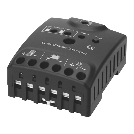
- Page 1 I N N O VAT I O N S FOR MOBILE LIFE Betriebsanleitung CD Serie Owner‘s Guide CD series Solar Laderegler Solar Charge Controller 85135...
-
Page 2: Table Of Contents
Inhalt Eigenschaften .................... 3 Erklärung zum Modell ................3 Produkt Beschreibung ................4 Montage und Anschluss ................4-6 Erdung des Systems .................. 7 Starten des Reglers .................7-8 Display und Funktionen ................8-9 Einstellungen ...................10 Fehlerbeschreibung ..................11 Empfohlene Sicherheitsbestimmungen ............12 Haftungsausschluss ..................12 Technische Daten ..................13... -
Page 3: Eigenschaften
Vielen Dank, dass Sie sich für unseren Solarladeregler aus der CD Serie entschieden haben, ein hochmodernes Gerät das nach den neuesten verfügbaren technischen Standards entwickelt wurde. Bevor Sie den Regler benutzen, lesen Sie bitte alle Anweisungen in diesem Handbuch. 1. Eigenschaften: •... -
Page 4: Produktbeschreibung
3. Produktbeschreibung Der Solarladeregler der CD Serie schützt die Batterie vor Überladung durch den Solargenerator und vor Tiefentladung durch die Verbraucher. Die Ladeeigenschaften umfassen verschiedene Stufen, die eine automatische Anpassung an die Umgebungstemperatur und das wählbare 12/24 V autom. Schaltermodell einschließen. 4. - Page 5 4.1.2 DIN-Schienenmontage Die Klemmplatte muss nach außen. Montieren Sie auf eine Standard-35-mm-DIN-Schiene. Drücken Sie die Klemmplatte nach innen und befestigen Sie den Regler auf der DIN Schiene. (Siehe nachstehende Bildbeschreibung) Hinweis: Die Dicke der DIN-Schiene sollte nicht mehr als 1 mm betragen, wir schlagen vor den 0,8 mm-Typ zu wählen.
- Page 6 4.3.Solar-Anlage und Regler verbinden Bitte beachten Sie! Die gesamte Leistung der Sonnenkollektoren sollte nicht mehr Leistungsauf- nahme (Spannung * Ampere - V * A) als der Regler haben! Schließen Sie die Kabel an die Solaranlage mit der richtigen Polarität an. Um Spannung auf den Kabeln zu vermeiden, zuerst den Regler und dann das Solar-Modul.
-
Page 7: Erdung Des Systems
5. Erdung des Solar Systems Solar Panel DC Ausgang Batterie Beachten Sie, dass die positiven Anschlüsse des Reglers intern verbunden sind und damit das gleiche elektrische Potential haben. Sollte eine Erdung erforderlich sein, muss dies immer auf den positiven Drähten geschehen. Hinweis: Wenn das Gerät in einem Fahrzeug verwendet wird, dessen negativer Batteriepol mit dem Chassis geerdet ist benötigen Verbraucher die mit dem Regler verbunden sind keine Masseverbindung zur Karosserie. -
Page 8: Display Und Funktionen
Batterietyp Der vorhandene Regler kann mit Bleibatterien und flüssigen Elektrolyten bedient werden. Wenn Sie beabsichtigen, eine Bleibatterie mit Festelektrolyt (Typ „Gel“ oder „Vlies“) zu nutzen, können Sie die Ladekennlinie einstellen (Siehe „settings“). Der Ladungsausgleich ist dann deaktiviert. Falls Sie Zweifel haben, wenden Sie sich an Ihren Händler. 7. - Page 9 7.2 Batterie Statusanzeiger CD Serie : 2 LEDs zeigen den Ladezustand der Batterie Erstes LED blinkt : Batteriekapazität <25% Erstes LED an : Batteriekapazität zwischen 25% und 75% Drittes LED an : Batteriekapazität >75% 7.3 Fehlersuche Fehler: LED blinkt bei einem offenen Stromkreis oder bei Überlastung oder Kurzschluss 7.4 DC Ausgangschalter Mit diesem Schalter wird der DC Ausgang an- und ausgeschaltet.
-
Page 10: Einstellungen
8. Einstellungen WARNUNG: Der Regler darf nicht offen sein, wenn er am Laufen oder eingesteckt ist! Vor dem Öffnen des Ladereglers immer die Sonnenkollektoren und die Batterie abklemmen. Die Steuerung kann für einen bestimmten Zweck konfiguriert werden. Laden Sie den Batterietyp Typ (Blei-Säure und Gel). Um dies zu tun, öffnen Sie den Boden des Reglers durch Entfernen der Schrauben auf der Rückseite! Wenn die Steuereinheit geöffnet ist, gibt es zwei Jumper auf der Platine. -
Page 11: Fehlerbeschreibung
9. Fehlerbeschreibung Symptom Display Ursache Abhilfe Niedriger Ladung wird fortgesetzt LED ist an Batteriestand wenn die Batterie (rotes LED) wieder geladen ist. Überstrom/-lastung Alle Verbraucher aus- schalten DC Ladungen Kurz- Beheben Sie den LED ist an schluss Kurzschluss, der Regler (rotes LED) schaltet sich automa- tisch nach 10 Sekun-... -
Page 12: Empfohlene Sicherheitsbestimmungen
10. Empfohlene Sicherheitsbestimmungen Verwendungszweck Der Laderegler ist ausschließlich für den Einsatz in Photovoltaik-Anlagen mit 12 V oder 24 V Normalspannung und nur in Verbindung mit belüfteten oder (VRLA) Bleibatterien vorgesehen. Der Regler wird während des Betriebs warm werden, aber es ist keine Wartung erforder- lich. -
Page 13: Technische Daten
12. Technische Daten Modell CD1215 CD2415 Normal Spannung 12 V 24 V Batteriewahl Load Battery with GEL Battery Load Battery with GEL Battery Liquid electrolyte Liquid electrolyte Ausgleichsspannung 14.5 ( 25° ) 14.3 ( 25° ) 29.0 ( 25° ) 28.6 ( 25°... - Page 14 Content 1. Features .................. 15 2. Model Explanation..............15 3. Products Description ..............16 4. Installation and Connection ..........16-18 5. Grounding the Sytem ...............19 6. Starting up the Controller ............ 19-20 7. Display and Functions ............20-21 8. Setting ..................22 9.
-
Page 15: Features
Thank you for choosing our CD series solar charge controller, it is a state of the art device which was developed according to the latest available technical stan- dards. Before using the controller, please read all instructions in this manual. -
Page 16: Products Description
3. Products Description CD series solar charge controller protects the battery from being overcharged by the solar array and from being deep discharged by the loads. The charging characteristics include serveral stages which include automatic adaption to the ambient temperature and 12/24 V auto. switch model selectable. - Page 17 4.1.2 DIN Rail Mounting Push the rail - clip outside then mount it on a standard 35 mm DIN rail. Push the rail - clip Inside to fasten the controller onto the DIN rail ( As below picures ) Note : The thickness of DIN rail should not more than 1 mm, suggest to choose the 0,8 mm type.
- Page 18 4.3 Solar array and Controller Connecting Please note that the solar panels total power should no more than the control- ler‘s rate power ( voltage*Amper - V*A ) ! Connect the wires leading to the solar array with correct polarity. To avoid any voltage on the wires, first connect the controller, then the solar array.
-
Page 19: Grounding The Sytem
5. Grounding the Solar System Solar Panel Battery DC Output Be aware that the positive terminals of the controller are connected internally and therefore have the same electrical potential. If any grounding is required, always do this on the positive wires. Note : If the device is used in a vehicle which has the battery negative on the chassis, loads connected to the regulator must not have an electric connection to the car body. -
Page 20: Display And Functions
Battery Type The controller is present to operate with lead acid batteries with liquid elect- rolyte. If you intend to use a lead-acid battery with solid electrolyte („gel“ type or „fleece“ type ) you can adjust the charging characteristics ( see „settings“ ). The equalization charge is deactivated then. - Page 21 7.2 Battery Status Indicator CD series : 2 LEDs show the state of the battery‘s charge First LED flashing : Battery capacity <25% First LED on : Battery capacity between 25% and 75% Third LED on : Battery capacity >75% 7.3 Fault Finding...
-
Page 22: Setting
8. Settings WARNING : The Controller should not be open when it is plugged in or running ! Always disconnect the solar panels and the battery before opening the charge controller. The controller can be configured for a particular purpose. Charge the battery type ( Lead -acid and Gel ) To do this, open the bottom of the controller by removing the screws on the back ! -
Page 23: Error Description
9. Error Description Error Display Reason Remedy Battery is low Load will reconnect LED is on as soon as battery ( red LED ) is recharged Overcurrent / Switch off all loads load DC loads short Remove the short LED is flashing circuit circuit, controller ( red LED ) -
Page 24: Recommended Safety And Application Procedures
10. Recommended Safety and Application Procedures Intended Use The charge controller is intended exclusively for use in photovoltaic systems with 12 V or 24 V normal voltage and in conjunction with vented or sealead ( VRLA ) lead acid batteries only. The controller will become warm when working but no maintenance is required. -
Page 25: Technical Data
12. Technical Data Model CD1215 CD2415 Nominal Voltage 12 V 24 V Battery Selection Load Battery with GEL Battery Load Battery with GEL Battery Liquid electrolyte Liquid electrolyte Equalization Volatage 14.5 ( 25° ) 14.3 ( 25° ) 29.0 ( 25° ) 28.6 ( 25°... - Page 26 Environmental Information for Customers in the European Union European Directive 2002/96/EC requires that the equipment bearing this symbol on the product and/or its packaging must not be disposed of with unsored municipal waste. The symbol indicates that this product should be disposed of separately from regular household waste streams.
- Page 28 www.reimo.com...
Need help?
Do you have a question about the CD Series and is the answer not in the manual?
Questions and answers