Table of Contents
Advertisement
Quick Links
Advertisement
Table of Contents

Related Manuals for Nordbo Robotics NAC-S20-15


Summary of Contents for Nordbo Robotics NAC-S20-15
- Page 1 NAC-S20-15 Active Compensation Unit User Manual Manual Version 1.0 For Software Version 1.1 Nordbo Robotics A/S info@nordbo-robotics.com Noatunvej 2 +45 81 81 98 81 5000 Odense, Denmark Copyright © 2021, Nordbo Robotics A/S. All Rights Reserved.
- Page 2 Copyright Copyright © 2021 Nordbo Robotics. All Rights Reserved. No part of this manual may be reproduced or transmitted in any form or by any means, electronic or mechanical, including photocopying and recording, for any purpose without the written permission of Nordbo Robotics.
-
Page 3: Table Of Contents
5.1. Connection Scheme, robots 5.2. Connection Scheme, PLC/IPC 5.3. Pneumatic Installation 5.4. Electrical Installation Controller Functions 6.1. Idle 6.2. Active Force Control 6.3. Retract 6.4. Load Calibration 2 of 44 NAC-S20-15 Active Compensation Unit - User Manual – Ver. 1.0... - Page 4 Control via Ethernet TCP/IP Interface Troubleshooting 9.1. Unable to Connect to the Controller 9.2. Reset Controller to Factory Defaults 9.3. Support Requests Technical Appendix 10.1. Connection Specifications 3 of 44 NAC-S20-15 Active Compensation Unit - User Manual – Ver. 1.0...
-
Page 5: Introduction
The product can only be used within the specified range. Using the product outside of its specified range may create unexpected results. Nordbo Robotics is not liable for any damage or injury resulting from the use of the product. -
Page 6: Product Information
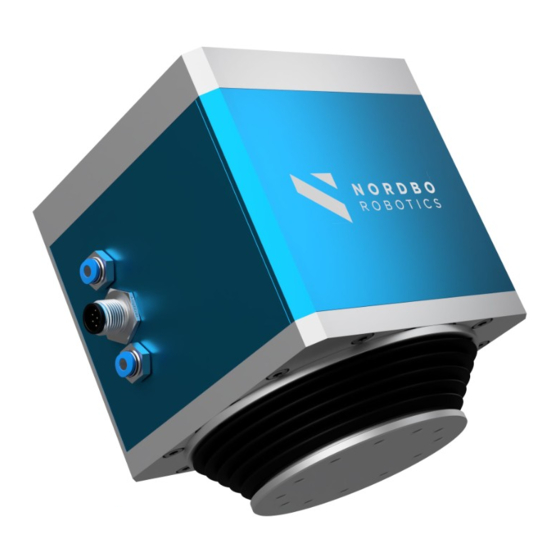
The force can be specified through the controller using IO or ethernet, and the integrated sensors ensure that high contact forces are prevented during initial part contact. Figure 1 – Tool Unit Figure 2 - Controller Figure 3 5 of 44 NAC-S20-15 Active Compensation Unit - User Manual – Ver. 1.0... -
Page 7: Included In The Package
NAC Cable Communication cable to connect the NAC-CTRL and the NAC-S20- IO modules IO modules that can be used directly with most common robot brands. Table 1 6 of 44 NAC-S20-15 Active Compensation Unit - User Manual – Ver. 1.0... -
Page 8: Technical Specifications
NAC-CTRL: IP40 with full pin allocations Table 2 Maximum possibly actuated force will be reduced when supply pressure is under nominal. At 0.1MPa the maximum actuated force is 25N 7 of 44 NAC-S20-15 Active Compensation Unit - User Manual – Ver. 1.0... -
Page 9: Mechanical Dimensions
Mounting Tool Side Bolts M5-10 Flange Diameter Ø60mm Mounting Fixation Site Bolts M5-10 Flange Diameter Ø60mm Table 3 Figure 4 Mounting Tool Side Mounting Fixation Side Figure 5 8 of 44 NAC-S20-15 Active Compensation Unit - User Manual – Ver. 1.0... -
Page 10: Nac-S20-15 Overview
Use the supplied cable to connect the tool unit and the controller. Air, out Connect tube for exhaust air Mounting hole pattern, tool Used when mounting a tool on the tool unit. side Table 4 9 of 44 NAC-S20-15 Active Compensation Unit - User Manual – Ver. 1.0... -
Page 11: Nac-Ctrl Interfaces
LED status indicator Power indicator. The LED is “On” when the NAC-CTRL is powered on. Reset button Hold to reset the controller to the default settings. Table 5 10 of 44 NAC-S20-15 Active Compensation Unit - User Manual – Ver. 1.0... - Page 12 NAC-CTRL Interface, Back Figure 8 Description Functionality Power supply input Use to power the NAC controller. IO interface Use to connect and control the NAC using inputs/outputs. Table 6 11 of 44 NAC-S20-15 Active Compensation Unit - User Manual – Ver. 1.0...
-
Page 13: Web Interface & Configuration
Diagnostics of NAC • Parameterization target forces selectable when using the IO interfaces • Updating the NAC-CTRL and NAC-S20-15 • Configuring Network settings for the NAC • Figure 9 12 of 44 NAC-S20-15 Active Compensation Unit - User Manual – Ver. 1.0... -
Page 14: Overview Of Web Interface
Update firmware on NAC control unit and Tool unit • About Firmware version number • Serial number • Table 7: Website tab functions for NAC web interface 13 of 44 NAC-S20-15 Active Compensation Unit - User Manual – Ver. 1.0... -
Page 15: How To Access The Web Interface
Connect the controller's power supply and connect to a PC using an ethernet cable. Step 2 Open Network & Internet settings by right-clicking on the Wi-Fi/LAN icon in the menu. Figure 11 14 of 44 NAC-S20-15 Active Compensation Unit - User Manual – Ver. 1.0... - Page 16 Step 3 Click ”Change adapter options”. Figure 12 Step 4 Right-click on ”Ethernet 3” and select “Properties.” Note: Ethernet number may vary from system to system Figure 13 15 of 44 NAC-S20-15 Active Compensation Unit - User Manual – Ver. 1.0...
- Page 17 Step 5 Select Internet Protocol Version 4 (TCP/IPv4) and click “Properties”. Figure 14 16 of 44 NAC-S20-15 Active Compensation Unit - User Manual – Ver. 1.0...
- Page 18 Set the IP address to 192.168.1.42 Set the Subnet mask to 255.255.255.0 Figure 15 Step 7 Access the real-time view using a browser by typing the IP address 192.168.1.42. Figure 16 17 of 44 NAC-S20-15 Active Compensation Unit - User Manual – Ver. 1.0...
-
Page 19: Configuring The Nac Using Web Interface
Navigate to the bottom of the configuration page and click “Save”. Step 3 Apply the new settings by rebooting the NAC-CTRL by powering it off and on again. 18 of 44 NAC-S20-15 Active Compensation Unit - User Manual – Ver. 1.0... -
Page 20: Configure Force Registers
4.2. Configure Force Registers Force registers enables the user to control the actuated force the NAC-S20-15 is applying by indexing to one of the 16 registers using the 4-force register selection digital input pins. Figure 18 Step 1 Edit each row in the Force register table Assign your target force. -
Page 21: Configure "Is Moving
Set distance threshold. The distance threshold corresponds to how far the actuator needs to move before the is moving signal goes low. Step 3 Navigate to the bottom of the configuration page and click “Save”. 20 of 44 NAC-S20-15 Active Compensation Unit - User Manual – Ver. 1.0... -
Page 22: Configuring Static Ip
Uncheck the box “Enable DHCP” so it is unset. Step 3 Enter the desired static IP address in the “IP address” field. Step 4 Enter the desired subnet mask in the “Subnet mask” field. 21 of 44 NAC-S20-15 Active Compensation Unit - User Manual – Ver. 1.0... -
Page 23: Configure Dhcp Client
DHCP server on the Network if any. Step 1 Click the checkbox “Enable DHCP” so it is set. Step 2 Navigate to the bottom of the configuration page and click “Save”. 22 of 44 NAC-S20-15 Active Compensation Unit - User Manual – Ver. 1.0... -
Page 24: Updating The Firmware
Click the “Browse…” button on the web page to select the downloaded update file. Figure 21 Step 4 Click the “Update” button. Step 5 Wait for the message “Firmware updated successfully”. 23 of 44 NAC-S20-15 Active Compensation Unit - User Manual – Ver. 1.0... - Page 25 Updating the NAC-S20-15 Firmware OBS! It is very important not to interrupt this process since it could place the NAC-S20-15 in a non-working state. The update process can take up to 5 min. Note: Risk of malfunctions and corrupted firmware if the NAC-S20-15 update process is interrupted.
-
Page 26: Installing The Nac-S20-15
5. Installing the NAC-S20-15 The following section describes how to install the NAC-S20-15 for a standard operation. The section will elaborate how pneumatic- and electrical installation is performed and the digital IO control interface for PLC control. Warning! Pneumatic and electric installations can cause unexpected movement of the NAC tool unit. -
Page 27: Connection Scheme, Robots
Supplies air to the NAC for it to be functional. Robot controller Supplies the system with power. Controls the force applied using Ethernet. NAC-CTRL Controls the active compensation unit. Table 9 26 of 44 NAC-S20-15 Active Compensation Unit - User Manual – Ver. 1.0... -
Page 28: Connection Scheme, Plc/Ipc
Controls the force applied using IO’s according to controlling I/O on NAC control unit settings configured in the web interface. Power supply unit 24V. Supplies the system with power. Table 10 27 of 44 NAC-S20-15 Active Compensation Unit - User Manual – Ver. 1.0... -
Page 29: Pneumatic Installation
NAC-S20-15. Step 2 To keep a IP67 rating the exhaust on the NAC-S20-15 must be attached to a 4 mm hose. The loose end of the hose must be placed in an environment protected against dust and liquids. -
Page 30: Electrical Installation
Table 11: Power supply connection with plug connector Step 2 Connect the loose end of the wire to the I/O terminal blocks of e.g., the robot controller. 29 of 44 NAC-S20-15 Active Compensation Unit - User Manual – Ver. 1.0... - Page 31 Power Supply Using External Power Supply The NAC-CTRL can be powered by using an external power supply according to the diagram. Figure 25: Connection of Digital IO interface with external user circuitry 30 of 44 NAC-S20-15 Active Compensation Unit - User Manual – Ver. 1.0...
- Page 32 Force register selection 4th bit Most significant bit. [MSB] ENABLE IN Enable active force control CALIB Calibrate Load weight ISMOV OUT Is moving ERROR OUT System error flag 31 of 44 NAC-S20-15 Active Compensation Unit - User Manual – Ver. 1.0...
-
Page 33: Controller Functions
Active Force Control When active force control is activated the NAC-S20-15 is regulated to apply the target force profile with a negative or positive force values. It is also possible to ramp linear up to or down to a target force value from a previous target. -
Page 34: Retract
It is important that the Tool unit is positioned so its stroke direction is aligned with the gravitational force. 33 of 44 NAC-S20-15 Active Compensation Unit - User Manual – Ver. 1.0... -
Page 35: Control Via Digital Io Interface
Determine Unit is Ready Readying the error signal from the controller is sufficient to decided when the unit is ready after powering on. Figure 27: Determine ready status 34 of 44 NAC-S20-15 Active Compensation Unit - User Manual – Ver. 1.0... -
Page 36: Active Force Control
Load Calibration for information on the calibration procedure. To initiate the calibration routine a pulse should be applied to the pin, but no longer than 2 seconds. 35 of 44 NAC-S20-15 Active Compensation Unit - User Manual – Ver. 1.0... -
Page 37: Monitor Nac-S20-15 Motion And Error
7.5. Monitor NAC-S20-15 Motion and Error Pin 9 can be used to monitor if the system NAC-S20-15 is moving. It will be logic high when the NAC-S20-15 is standing still and logic low when NAC-S20-15 is moving. Pin 10 can be used to monitor if the systems is in an error state. It will be logic high if there is no error state and logic low if it is in an error state. -
Page 38: Control Via Ethernet Tcp/Ip Interface
• Monitor if the NAC-S20-15 is in motion • Monitor the stroke distance • Monitor the NAC-S20-15 angle relative to the gravity vector The NAC can be controlled through an Ethernet interface using a simple protocol on a standard TCP/IP connection. Data is transmitted using port 2002. The protocol uses only the data types seen in the table below. - Page 39 -110000 … 150000 between sending a UINT8 vs sending a INT32. 0x03 Retract Signals the NAC to lift the load weight and tares the position encoder when fully retracted. 38 of 44 NAC-S20-15 Active Compensation Unit - User Manual – Ver. 1.0...
- Page 40 NAC- S20-15. 0x22 Angle DOUBLE Angle [m] The current angle of data the NAC-S20-15 relative to the gravitational vector. 39 of 44 NAC-S20-15 Active Compensation Unit - User Manual – Ver. 1.0...
- Page 41 UINT8[4] UINT8[0] = 1, Returns the firmware version UINT8[1] = Major, version of the NAC- UINT8[2] = Minor, CB firmware. UINT8[3] = Patch Table 15: Message Types 40 of 44 NAC-S20-15 Active Compensation Unit - User Manual – Ver. 1.0...
-
Page 42: Troubleshooting
IP address. If this is the case, use the reset button to reset IP address to 192.168.1.100. Step 3 Try using an IP Scanner software to scan your network to identify the IP of the NAC-CTRL. 41 of 44 NAC-S20-15 Active Compensation Unit - User Manual – Ver. 1.0... -
Page 43: Reset Controller To Factory Defaults
For questions, feature requests, and general support, please visit support.nordbo.io and create a ticket. We highly value feedback on our products and you can help us improve the product by sharing your experience. 42 of 44 NAC-S20-15 Active Compensation Unit - User Manual – Ver. 1.0... -
Page 44: Technical Appendix
Standard ports Web server Control interface 2002 Maximum cable length 30 m Tool unit interface Connection plug M8 8-pin female Maximum cable length Table 18: Connectors and specifications 43 of 44 NAC-S20-15 Active Compensation Unit - User Manual – Ver. 1.0... - Page 45 Nordbo Robotics A/S info@nordbo-robotics.com Noatunvej 2 +45 81 81 98 81 5000 Odense, Denmark Copyright © 2021, Nordbo Robotics A/S. All Rights Reserved.
Need help?
Do you have a question about the NAC-S20-15 and is the answer not in the manual?
Questions and answers