Table of Contents

Related Manuals for Nordbo Robotics Mimic


Summary of Contents for Nordbo Robotics Mimic
- Page 1 Mimic Kit for Universal Robots User Manual Manual Version 2.3 For Software Version 2.2 Nordbo Robotics A/S info@nordbo-robotics.com Noatunvej 2 +45 81 81 98 81 5000 Odense, Denmark Copyright © 2021, Nordbo Robotics A/S. All Rights Reserved.
- Page 2 Copyright Copyright © 2021 Nordbo Robotics. All Rights Reserved. No part of this manual may be reproduced or transmitted in any form or by any means, electronic or mechanical, including photocopying and recording, for any purpose without the written permission of Nordbo Robotics.
-
Page 3: Table Of Contents
Using the Track node 6.4. Using the Teach node 6.5. Using the Tune node 6.6. Using the Play node Introduction to the web interface 7.1. Real-Time View 7.2. Record Mimic Kit for Universal Robots - User Manual – Ver. 2.3 2 of 66... - Page 4 7.3. Hemisphere 7.4. Network 7.5. About How to access the web interface Troubleshooting Mimic Kit for Universal Robots - User Manual – Ver. 2.3 3 of 66...
-
Page 5: Introduction
Before attempting to connect the Mimic kit to the robot, it is important to ensure that the robot cannot unintentionally. The robot must therefore be powered off before attempting to connect the sensors to the robot. -
Page 6: Product Information
2.1. Mimic kit introduction The Mimic kit uses a unique electromagnetic sensor that does not require line of sight, enabling users to record and replicate complex movements that are challenging to automate. The Mimic kit records both orientation and rotation, drastically reducing the time spent programming and reprogramming. -
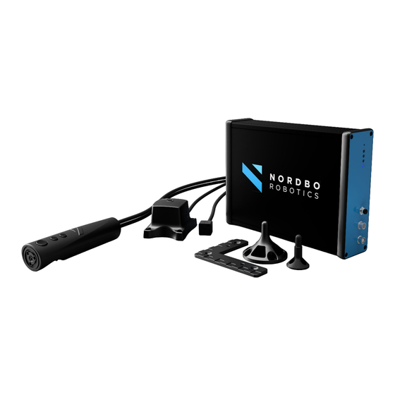
Page 7: Mimic Kit Content
4x M6-10 mm stainless steel Joystick (black nylon bolts) or robot bolts (stainless steel bolts). 3m 6-pole cable, open- Cable connect Mimic ended Controller to the robot's I/O ports. Mimic Kit for Universal Robots - User Manual – Ver. 2.3 6 of 66... -
Page 8: Technical Specifications
Note: The recommended sensor distance is 500 mm although the functioning range of the sensor is up to 1 meter. Be aware that the increasing the distance between receiver and transmitter will decrease precision and increase noise. Figure 2 Mimic Kit for Universal Robots - User Manual – Ver. 2.3 7 of 66... - Page 9 “front” by default but can be changed using the web-interface. See Section 7.3 Hemisphere for more information. An overview of the 4 different hemisphere options Bottom Front Back Mimic Kit for Universal Robots - User Manual – Ver. 2.3 8 of 66...
-
Page 10: Npt-Ctrl Interface
Voltage Input Receptacle for supplying power. Always use the included power supply or 9-36V at 15W. Compatible with barrel jack using 2,1 mm ID 5,5 mm OD. Mimic Kit for Universal Robots - User Manual – Ver. 2.3 9 of 66... -
Page 11: Connecting To Ur Robots
Identify the reach of the robot in the robot installation manual and ensure that people and objects are outside this distance. Mimic Kit for Universal Robots - User Manual – Ver. 2.3 10 of 66... - Page 12 OBS! The wire from the transmitter must be placed parallel to the wire from the robot. This makes sure that the Mimic and robot is aligned in movement. This is a default and can be changed as described in Section 5.2 Setup Transmitters.
- Page 13 Connect the transmitter’s cable to the TX-input controller. Figure 9 Step 4 Use the supplied RJ45 ethernet cable and connect the Mimic Controller to the robot control box. Mimic Kit for Universal Robots - User Manual – Ver. 2.3 12 of 66...
- Page 14 Connect the power supply to the Mimic Controller’s VIN-input. Figure 11 Step 6 Connect the supplied 6-pole M8 wire to the JOUT on the Mimic Controller. Figure 12 Mimic Kit for Universal Robots - User Manual – Ver. 2.3 13 of 66...
- Page 15 Click Apply. The text saying "Not connected to network!" should now change to "Network connected!”. If it does not, please check that the leftmost light (ID 1) on the Mimic Kit is on. If it is off, it means that there is a loose connection between the robot and the Mimic Kit.
- Page 16 Figure 15 Mimic Kit for Universal Robots - User Manual – Ver. 2.3 15 of 66...
-
Page 17: Installing Urcap
4. Installing URCap The software required for using the Mimic kit on Universal Robots is called a URCap. The URCap “nptmimic-X.X.X.urcap” is located on the USB delivered with the Mimic kit. Follow the steps in this section to install the URCap on a Universal Robot e-series. - Page 18 Step 3 Click “Settings”. Figure 17 Step 4 Navigate to System in the left menu and select URCaps. Mimic Kit for Universal Robots - User Manual – Ver. 2.3 17 of 66...
- Page 19 Click the “+” at the bottom left corner to open a file browser. Step 6 Locate the USB memory and select nptmimic.urcap. Click open when highlighted. Mimic Kit for Universal Robots - User Manual – Ver. 2.3 18 of 66...
- Page 20 Figure 19 Mimic Kit for Universal Robots - User Manual – Ver. 2.3 19 of 66...
- Page 21 Step 7 After installing a pop-up will be displayed with the text “The changes require a restart to take effect.” Restart the robot by clicking the “Restart”. After restarting, the Mimic URCap will be installed on the robot. Figure 20 Mimic Kit for Universal Robots - User Manual –...
-
Page 22: Configuring The Installation
5. Configuring the installation All settings and options to modify the Mimic URCap can be found under Installation by selecting URCaps and Nordbo Mimic in the menu. The settings are categorized into five different tabs: General • Setup • Trajectories •... -
Page 23: Configuring The General Settings
Check the box “Enable Nordbo Mimic control” to enable use. Step 3 Insert the Mimic IP address. The default static IP address is 192.168.1.100 unless a custom IP address has been defined. Mimic Kit for Universal Robots - User Manual – Ver. 2.3... - Page 24 Step 5 Click the “Check Connection” button to verify the connection to the Mimic Controller. Step 6 (Optional) In some cases, it may be beneficial to increase the smoothing of the recorded movement. The user can filter noise in the estimated position, by using the average of the latest recorded positions as one position.
-
Page 25: Setup Transmitters
(see Figure 24). This option is always available in the Track and Tune nodes and is called “Robot Base". Mimic Kit for Universal Robots - User Manual – Ver. 2.3 24 of 66... - Page 26 Figure 24 Mimic Kit for Universal Robots - User Manual – Ver. 2.3 25 of 66...
-
Page 27: Managing Saved Trajectories
Trajectories created using the Track node. In the tabs, you can rename, make copies of Trajectories, delete Trajectories, or reset the tuning applied to Trajectories. Figure 25 Mimic Kit for Universal Robots - User Manual – Ver. 2.3 26 of 66... -
Page 28: Calibrating Workspaces
The Robot Workspace tab is used to specify where to execute Trajectories that have been recorded using the Mimic Teach node. When using the Teach node, the Trajectory is recorded relative to the Calibration Plate. When executing the Trajectory with a Play or Tune node, it is executed relative to the Calibration Plate. -
Page 29: Adding A Robot Workspace
(Transmission Control Protocol) under “Installation“ in the tab “General”. Note: If a TCP for the calibration tool has not yet been created, then create a new TCP and calibrate it. Mimic Kit for Universal Robots - User Manual – Ver. 2.3 28 of 66... - Page 30 The values can be inserted automatically by clicking the “Calibrate” button. The following steps elaborate the calibration routine. Note: It is strongly recommended to use the calibration routine for maximal precision. Figure 29 Mimic Kit for Universal Robots - User Manual – Ver. 2.3 29 of 66...
- Page 31 Calibration Plate (one being I, two being II, and three being III). Figure 30 Mimic Kit for Universal Robots - User Manual – Ver. 2.3 30 of 66...
- Page 32 Figure 31 Step 6 Repeat this process for the remaining points and click Done follow by Save. The calibration will not be saved if Cancel is clicked. Mimic Kit for Universal Robots - User Manual – Ver. 2.3 31 of 66...
-
Page 33: Setting Up The Joystick
Note: This step guide requires the digital inputs on the robot to be connected the same way as explained in Step 7 in Section 3.1 Connecting the Mimic kit to the robot. If the wires are connected differently, these changes also apply to this Section. - Page 34 Note: The mapping can be changed by changing the index in the combo box. The index is the number of the digital input number. Figure 33 Power Wire color Grey Blue Black White Brown Default digital input Default Move Backward Forward Record mapping Mimic Kit for Universal Robots - User Manual – Ver. 2.3 33 of 66...
-
Page 35: Configuring Outputs
Outputs tab. All outputs are selected, and recorded, by default. Remember to deselect the outputs that should not be recorded, if any. Note: In Figure 34 the Digital Outputs 4, 5, 6 and 7 will not be recorded. Figure 34 Mimic Kit for Universal Robots - User Manual – Ver. 2.3 34 of 66... -
Page 36: Robot Program Nodes
The following Section describes the process of creating a program using the Mimic kit. The four Mimic nodes can be seen in the menu to the left under URCaps. The table on the following page gives an overview of the different nodes and what they can do. - Page 37 This is necessary if the operator wishes to tune the precision of a recorded Trajectory. Play The Play node executes Trajectories recorded using the Teach and Track nodes. Mimic Kit for Universal Robots - User Manual – Ver. 2.3 36 of 66...
-
Page 38: How Outputs Are Captured
Trajectory except for those deselected in the Outputs tab in the installation. Figure 36 Step 1 Click on Robot Program at the top of the program tree. Mimic Kit for Universal Robots - User Manual – Ver. 2.3 37 of 66... - Page 39 Click on Advanced in the left menu and add a Thread. Step 3 Add a "Set" command and make it set the desired output equal to the selected input. Mimic Kit for Universal Robots - User Manual – Ver. 2.3 38 of 66...
-
Page 40: General Information About Nodes
Installation. The Robot Base option means that the Transmitter’s wire is aligned with the wire at the Robot Base. Step 5 Click the “Show Runtime View" button. Mimic Kit for Universal Robots - User Manual – Ver. 2.3 39 of 66... - Page 41 Step 2 Click the play button at the bottom of the screen to start the program. Mimic Kit for Universal Robots - User Manual – Ver. 2.3 40 of 66...
- Page 42 Click and hold the button on the Joystick which is assigned to the “Move” input (according to Section 5.6 Setting up the Joystick). The robot will Mimic the movements of the Joystick. Alternately, use the “Start Track” button on the Teach Pendant.
- Page 43 Trajectory is automatically saved once the program is stopped. Step 11 (Optional) Delete or suppress the Track node if wanting to play or tune the recorded Trajectory using the Play or Tune node. Mimic Kit for Universal Robots - User Manual – Ver. 2.3 42 of 66...
- Page 44 Figure 38 Mimic Kit for Universal Robots - User Manual – Ver. 2.3 43 of 66...
-
Page 45: Using The Teach Node
Write a unique name for the Trajectory in the "Choose a name" text field. Step 2 Select which Joystick to use. Step 3 Click the “Show Runtime View” button. Figure 39 Mimic Kit for Universal Robots - User Manual – Ver. 2.3 44 of 66... - Page 46 Teach Pendant. When either button is clicked, the color of the “Start Recording” button will change to red, indicating that a program is being recorded. Step 4 Perform the movements you wish to record. Mimic Kit for Universal Robots - User Manual – Ver. 2.3 45 of 66...
- Page 47 Step 7 (Optional) Delete or suppress the Teach node if wanting to play or tune the recorded Trajectory using the Play or Tune node. Figure 41 Mimic Kit for Universal Robots - User Manual – Ver. 2.3 46 of 66...
-
Page 48: Using The Tune Node
If the Trajectory was recorded using Teach, then select in which robot workspace the robot should execute the Trajectory. Step 6 Click the “Show Runtime View” button. Mimic Kit for Universal Robots - User Manual – Ver. 2.3 47 of 66... - Page 49 Use the “Forward” and “Backward” buttons on the Teach Pendant or on the Joystick to move the robot back and forth, following the Trajectory (see Section 5.6 Setting up the Joystick). Mimic Kit for Universal Robots - User Manual – Ver. 2.3 48 of 66...
- Page 50 Note: Per default, the orientation of the robot is locked while moving. To unlock it, click the “Activate” button in the "Tune Orientation” row. Step 4 Repeat steps 2 and 3 until the program is tuned. Figure 43 Mimic Kit for Universal Robots - User Manual – Ver. 2.3 49 of 66...
- Page 51 "Override Outputs", selecting which outputs should be active, and then moving between two points in the Trajectory. The active outputs will then be set to the selected outputs in the interval between the two points. Mimic Kit for Universal Robots - User Manual – Ver. 2.3 50 of 66...
- Page 52 Note: Changing the outputs while “Override Outputs" is active corresponds to saving the current interval with the old outputs and starting a new interval with the new outputs. Figure 44 Mimic Kit for Universal Robots - User Manual – Ver. 2.3 51 of 66...
- Page 53 Trajectory and saved. To reset the tuning, stop the program and click the “Reset Tuning” button. This deletes all changes to the Trajectory. Mimic Kit for Universal Robots - User Manual – Ver. 2.3 52 of 66...
-
Page 54: Using The Play Node
Note: Make sure the part is placed in the exact same location, relative to the Calibration Plate, as it was during the teaching of the Trajectory. Step 4 Click the “Show Runtime View” button. Mimic Kit for Universal Robots - User Manual – Ver. 2.3 53 of 66... - Page 55 Figure 45 Runtime View Step 1 Click the play button at the bottom of the screen to start executing the Trajectory. Mimic Kit for Universal Robots - User Manual – Ver. 2.3 54 of 66...
- Page 56 Step 2 (Optional) Adjust the robot’s movement speed by adjusting the slider at the lower center of the screen. Figure 46 Mimic Kit for Universal Robots - User Manual – Ver. 2.3 55 of 66...
-
Page 57: Introduction To The Web Interface
A live view of the transmitter and the receiver illustrates any movement of the sensor. Below the 3D view is the current position of the receiver relative to the transmitter. Figure 47 Mimic Kit for Universal Robots - User Manual – Ver. 2.3 56 of 66... -
Page 58: Record
The record page allows recording of the receiver’s movements. Using the “Start” and “Stop” buttons, the user can record a movement and export the movement as a CSV file. Figure 48 Mimic Kit for Universal Robots - User Manual – Ver. 2.3 57 of 66... - Page 59 It is only possible to track movements inside the selected hemisphere. Be aware of which hemisphere is selected before trying to record a Trajectory! Bottom Front Back Figure 49 Mimic Kit for Universal Robots - User Manual – Ver. 2.3 58 of 66...
- Page 60 Click Save once complete to apply the configuration. Note: Enabling DHCP will change the IP address. The Mimic Controller cannot be accessed without knowing the IP address. The user must therefore be able to identify the assigned IP address to access the Mimic Controller after enabling DHCP.
- Page 61 The network page allows the user to see more information about the specific product's firmware version and serial numbers. From this page, the user can update the firmware by uploading files supplied by Nordbo Robotics. Figure 51 Mimic Kit for Universal Robots - User Manual – Ver. 2.3 60 of 66...
- Page 62 8. How to access the web interface The Mimic Controller can be accessed through an internet browser by typing in the IP address of the Mimic Controller. Before the controller can be accessed, the network settings may need to be configured.
- Page 63 Click ”Change adapter options”. Figure 53 Step 4 Right-click on ”Ethernet 3” and select “properties.” Note: "Ethernet 3" may have a different number than “3”. Figure 54 Mimic Kit for Universal Robots - User Manual – Ver. 2.3 62 of 66...
- Page 64 Step 5 Select Internet Protocol Version 4 (TCP/IPv4) and click “Properties”. Figure 55 Mimic Kit for Universal Robots - User Manual – Ver. 2.3 63 of 66...
- Page 65 Set the IP address to 192.168.1.101 Set the Subnet mask to 255.255.255.0 Figure 56 Step 7 Access the real-time view using a browser by typing the IP address 192.168.1.100. Figure 57 Mimic Kit for Universal Robots - User Manual – Ver. 2.3 64 of 66...
- Page 66 Unable to connect to Mimic? Check that all cables are properly connected. • Restart the Mimic Controller by unplugging and plugging the power back in. • IP of the robot might be wrong. xxx.xxx.xxx.yyy all x's must be the same for both the robot/computer •...
- Page 67 Nordbo Robotics A/S info@nordbo-robotics.com Noatunvej 2 +45 81 81 98 81 5000 Odense, Denmark Copyright © 2021, Nordbo Robotics A/S. All Rights Reserved.
Need help?
Do you have a question about the Mimic and is the answer not in the manual?
Questions and answers