Advertisement
Quick Links
Advertisement

Related Manuals for CLA-VAL 39A


Summary of Contents for CLA-VAL 39A
- Page 1 OWNERS MANUAL...
-
Page 2: Table Of Contents
CONTENTS Introduction 39A ir valve placement Valve sizing for 39A valves General rrangement and imensions Troubleshooting Spares ist and torque figures Maintaining the alve 7 17... -
Page 3: Introduction
O-ring suppliers. The valve has an integral anti slam feature specifically sized for bulk water pipelines. The 39A, if correctly sized and placed, will offer surge protection in the event of rapid filling of pipelines and surge events such as pump trip. -
Page 4: Ir Valve Placement A
39A AIR VALVE PLACEMENT Reservoir Peak / High point River crossing Break in slope Isola ng Valve Air Valve Check Valve Centrifugal Pump Under road Submersible Pump Peaks/ igh points The most important areas to place air valves are high points or peaks along the pipeline. Air will always rise to these points when filling and when the pipeline is operating. -
Page 5: Valve Sizing For 39A Valves
VALVE SIZING Velocity /s 12" 2" 8" 1" 4" 10" 6" 3" How To Use the Chart Select pipe size and velocity, use either maximum flow velocity or calculate drainage velocity based on drainage or expected potential rupture. Where the pipe size and velocity intersect there will be a colour band, match the colour band to the valve size in the legend below. -
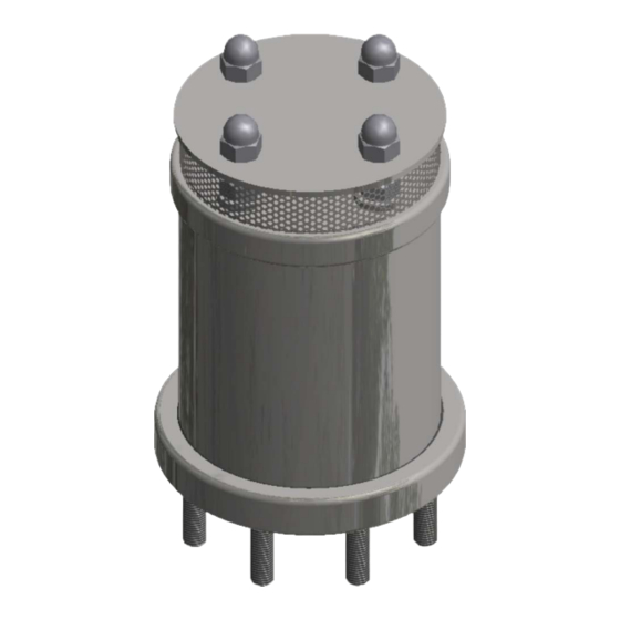
Page 6: General Rrangement And Imensions A D
SERIES 39A General rrangement and imensions Nuts SS 316 Top Cover S 316 Screen Mesh S 316 Top Flange SS 316 O- ing NBR/EPDM Tie Rods SS 316 Anti Slam Float HDPE Nozzle Float HDPE Nozzle SS 316 Nozzle Seat EPDM Control Float HDPE Baffle Plate SS 316... -
Page 7: Troubleshooting
TROUBLE SHOOTING In general the 39A v alve will leak as an indication of a problem. As such the first thing that needs to be done is define what we consider leaking: Air valves will always pass some water vapour when discharging pressurised air his vapour may accumulate within the top of the air valve and offer the appearance of leaking. - Page 8 Problem Cause Comments Solution Valve leaking Damage to O-ring or On occasion, debris Follow maintenance constantly. nozzle seat or nozzle. may pass into the instructions and valve and pass out replace damaged item. freely. After a while, however, during the time the debris is trapped in the valve, an O-ring seal or other...
- Page 9 MAINTAINING THE VALVE Warning solate the valve before commencing any work 1. Before doing any maintenance on the valve make sure the valve is isolated from pressure . Dome Nuts 2. Remove the uts from the valve...
- Page 10 3. Remove the op ap from the valve 4. Remove the creen esh from valve.
- Page 11 If O-ring’s offer a lot of resistance when removing lubricate with water 5. Remove yloc nuts , ashers and O-rings from ie rods 6. Remove the op lange , be aware that some pressure may still be trapped in the valve. Open cautiously, initially pulling the flange up and away from you.
- Page 12 7. Check op lange O-ring If damaged replace with new O-ring 8. Check valve internals for obvious debris and clear .
- Page 13 9. Remove arrel, be aware when removing the barrel that water may still be inside and will spill as you lift the barrel. 10. Remove float set .
- Page 14 11. Check nti lam O-rings top and bottom and replace if necessary 12. Check ozzle for blockages his can be simply done by holding the nozzle up to the sun and seeing if light is visible through the orifice. If the nozzle is blocked then clean with thin wire or paperclip.
- Page 15 If you do not have a spare nozzle seat available simply flip the existing seat over 13. Check the Nozzle Seat in the lower float for any damage, to the surface, remove and replace. 14 Check ottom lange arrel O-ring and replace necessary...
- Page 16 Control Float Nozzle Float Anti-Slam Float Nozzle Seat Nozzle 15. Replace the float stack, ontrol loat (lower float) first with the nozzle seat facing upward. Then the ozzle loat with nozzle facing downwards and finally the nti lam float. Making sure that one O-ring makes contact with the surface of the ozzle loat.
- Page 17 17. Replace the op lange, making sure the arrel fits snugly into the O-ring groove and does not slide to the extreme side of the ottom lange O-ring groove while fitting. If the barrel has moved, lightly tap until centered again. Nyloc Nuts Washers O-rings...
- Page 18 19. Replace the creen esh, making sure the mesh fits snugly into the mesh groove. 20. Replace the top cap.
- Page 19 21. Replace nuts. Hand or lightly tighten. There is no need to torque these nuts, they are there to keep the top cap on only. 22. Reopen the isolating valve slowly. Be aware that high air discharge may occur when reopening and that some spray may occur as pressure builds in the valve.
- Page 20 0003 1220 CLA-VAL Global Headquarters, 1701 Placentia Avenue, Costa Mesa, CA, 92627, Phone: (949) 722 - 4800, (800) 942 - 6326, Fax: (949) 548 5441, Email: info@cla-val.com Cla-Val 201 Printed in USA Specifications subject to change without notice.
Need help?
Do you have a question about the 39A and is the answer not in the manual?
Questions and answers