
Related Manuals for EnerSys alpha Matrix C16


Summary of Contents for EnerSys alpha Matrix C16
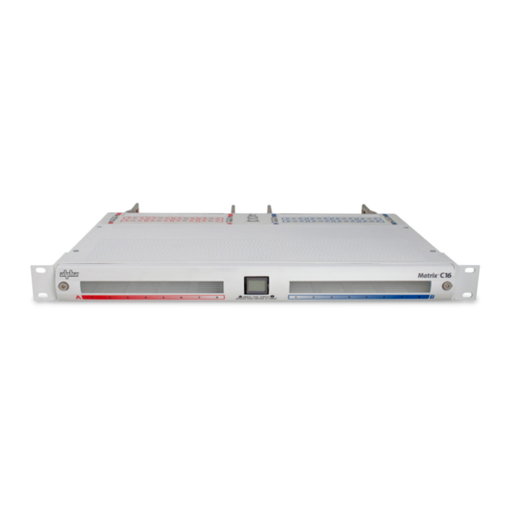
- Page 1 Matrix C16 ™ High Density Connectorized DC Distribution Breaker Panel Technical Manual Effective: January 2020...
- Page 2 Safety Notes Alpha Technologies Services, Inc. considers customer safety and satisfaction its most important priority. To reduce the risk of injury or death and to ensure continual safe operation of this product, certain information is presented differently in this manual. Alpha tries to adhere to ANSI Z535 and encourages special attention and care to information presented in ®...
- Page 3 Matrix C16 ™ High Density Connectorized DC Distribution Breaker Panel Technical Manual C048-725-30 Rev. B Effective: January 2020 © 2020 by Alpha Technologies Services, Inc. Disclaimer Images contained in this manual are for illustrative purposes only. These images may not match your installation. Operator is cautioned to review the drawings and illustrations contained in this manual before proceeding.
-
Page 4: Table Of Contents
Contents 1.0 Purpose and Applicability � � � � � � � � � � � � � � � � � � � � � � � � � � � � � � � � � � � � � � � � � � � � � � � � � 1�1 Product Model �... - Page 5 6.0 Operation (Models with LED Display) � � � � � � � � � � � � � � � � � � � � � � � � � � � � � � � � � � � � � � � 6�1 Layout and Function of Logic PCB Interface �...
-
Page 6: Purpose And Applicability
1.0 Purpose and Applicability Purpose and Applicability The purpose of this document is to detail the installation and operation instructions for the Matrix C16 breaker panel� ™ 1.1 Product Model Product Model This document applies to the following configurations of the Matrix C16 breaker panel: Table 1. Matrix C16 Model Configurations PART NUMBER DESCRIPTION C016-1621-10 Matrix C16;... -
Page 7: Installation
4.0 Installation Installation 4.1 Installation Preparation Installation Preparation When selecting an installation location, ensure that all of the following conditions are met before proceeding� 4.1.1 4.1.1 Elevated Operating Ambient Temperature Elevated Operating Ambient Temperature If you install the panel in a closed or multi-unit rack assembly, the operating ambient temperature of the rack environment may be greater than room ambient�... -
Page 8: 4�2 Mechanical Mounting
4.2 Mechanical Mounting Mechanical Mounting NOTICE: THIS PRODUCT MUST BE INSTALLED WITHIN A RESTRICTED ACCESS LOCATION WHERE ACCESS IS THROUGH THE USE OF A TOOL, LOCK AND KEY, OR OTHER MEANS OF SECURITY, AND IS CONTROLLED BY THE AUTHORITY RESPONSIBLE FOR THE LOCATION�... -
Page 9: 4�2�3 Optional Rear Rack Support Kit (C750-284-10)
4.2.3 4.2.3 Optional Rear Rack Support Kit Optional Rear Rack Support Kit (C750-284-10) (C750-284-10) The optional rear rack support kit provides additional support to the rear of the panel by mounting to the rear rack posts� An adjustable cable lacing bar is included� Step 1. -
Page 10: 4�3 Ground Installation
4.3 Ground Installation Ground Installation CAUTION! DO NOT ENERGIZE THE PANEL BEFORE CHASSIS GROUND IS CONNECTED� The chassis ground is located on each side of the panel� A two hole lug landing position is provided per side� See table below for termination information. A minimum of #6 AWG chassis ... -
Page 11: 4�4 Input Connections
4.4 Input Connections Input Connections WARNING! ELECTRICAL HAZARD TO PROTECT PERSONNEL AND EQUIPMENT, ENSURE ALL INPUT POWER FEEDS ARE NOT ENERGIZED BEFORE INSTALLING THEM� ELECTRICAL INSTALLATION SHOULD ONLY BE PERFORMED BY QUALIFIED PERSONNEL WITH PROPER TOOLS AND PROTECTIVE SAFETY EQUIPMENT� NOTICE: MAKE SURE THAT ALL FEEDER CABLES HAVE HEAT SHRINK APPLIED PRIOR TO TERMINATION,... -
Page 12: 4�5 Rear Plastic Safety Shields
4.5 Rear Plastic Safety Shields Rear Plastic Safety Shields WARNING! ELECTRICAL HAZARD FAILURE TO INSTALL THE PLASTIC SAFETY SHIELDS PROPERLY MAY CREATE AN ELECTRICAL HAZARD� THE PANEL MAY BE ENERGIZED WHEN INSTALLING THE REAR PLASTIC SAFETY COVERS� USE INSULATED TOOLS AND APPROPRIATE PERSONAL PROTECTIVE EQUIPMENT WHEN INSTALLING OR REMOVING THE REAR PLASTIC SAFETY COVERS�... -
Page 13: 4�7 Alarm Installation
4.7 Alarm Installation Alarm Installation The Matrix C16 has Form-C dry alarm contacts for remote alarm monitoring� An 8p8c- (RJ-45) modular jack can be found in the center of the panel when viewed from the rear� It is the lower of the two jacks as shown in Figure 14� Plug a Cat 5/5e/6 UTP cable with a TIA/EIA T568B termination into the alarm jack�... -
Page 14: 4�9 Installing The Network Cable
4.9 Installing the Network Cable Installing the Network Cable If remote monitoring over the network is required, complete the following steps to connect the Ethernet module with embedded web server� NOTE: For initial configuration, it is recommended to use a crossover Cat 5/5e/6 UTP cable to connect a laptop directly to the Ethernet port of the Matrix panel. If the laptop is configured ... -
Page 15: Operation (Models With Smartswitch)
5.0 Operation Operation (Models with SmartSwitch) (Models with SmartSwitch) Operation instructions for models without the SmartSwitch controller can be found in Section 6.0 “Operation (Models with LED Display)” on Page 21. If you are using the Ethernet based web server, see Section 5�6 “Review System Status via the Embedded Web Server"... -
Page 16: 5�3 Initial Operation
5.3 Initial Operation Initial Operation Once all breakers are installed and power is present on the inputs, remove the breaker compartment door and slide the power switch to the on position� The power switch is located on the front right side of the SmartSwitch� The display will turn on and display the Alpha logo ®... -
Page 17: 5�4 "View Bkr Load Hold 3 S
5.4 “VIEW BKR LOAD HOLD 3 S” “VIEW BKR LOAD HOLD 3 S” VIEW BKR Entering this menu will display voltage, current, and alarm status LOAD information for each circuit that is stored in inventory� When the menu HOLD 3 S is entered, the first circuit in inventory will be displayed. Tapping the ... -
Page 18: 5�5�5 "Setup Advanced Hold 3 S" - Advanced Settings Menu
5.5.5 5.5.5 “SETUP ADVANCED HOLD 3 S” – “SETUP ADVANCED HOLD 3 S” – Advanced Settings Menu Advanced Settings Menu SETUP The advanced menu contains the following functions� ADVANCED Changing these settings or using these functions may HOLD 3 S affect the monitoring capabilities of the panel. -
Page 19: 5�6�2 Navigating The Web Server
5.6.2 5.6.2 Navigating the Web Server Navigating the Web Server Upon loading the Matrix web server, the Realtime Status page will be displayed� Click on the “Administration” tab to view or modify settings� 5.6.3 5.6.3 Administration Settings Administration Settings When accessing the web server for the first time, it is necessary to configure the administration settings. Click ... -
Page 20: 5�7 Smartswitch User Interface Map
5.7 SmartSwitch User Interface Map SmartSwitch User Interface Map FROM STANDBY: ┣ (Input A Display) ┣ (Input B Display)** ┣ VIEW BKR LOAD HOLD 3S ┃ ┣ (A1 / 01*) ┃ ┣ (A2 / 02*) ┃ ┣ (A3 / 03*) ┃ ... -
Page 21: Operation (Models With Led Display)
6.0 Operation Operation (Models with LED Display) (Models with LED Display) 6.1 Layout and Function of Logic PCB Interface Layout and Function of Logic PCB Interface Breaker Inventory Reset Button Blue LED (Behind (Behind Beeper) Button) Breaker A Input Trip Power Red LED Blue LED... -
Page 22: 6�2 To Inventory The Circuit Breakers
6.2 To Inventory the Circuit Breakers To Inventory the Circuit Breakers 1� From the factory, when power is applied to the panel for the first time, the blue Breaker Inventory LED will flash at about a one second interval� This indicates that it is necessary to inventory the circuit breakers that are installed in the panel� 2� Turn on all the circuit breakers that are installed in the panel� Press and hold the Breaker Inventory button� Hold the button down until the blue Breaker Inventory LED turns on, then subsequently turns off (about five seconds). ... -
Page 23: Maintenance Operations
7.0 Maintenance Operations Maintenance Operations 7.1 Breaker Removal Breaker Removal CAUTION! THE PANEL MAY BE ENERGIZED� THE PANEL SHOULD ONLY BE SERVICED BY QUALIFIED PERSONNEL WITH INSULATED TOOLS AND APPROPRIATE PERSONAL PROTECTIVE EQUIPMENT� ONLY REMOVE A BREAKER ONCE IT IS TURNED OFF� Figure 19. -
Page 24: Product Specifications
8.0 Product Specifications Product Specifications Table 6. Technical Specifications Electrical Voltage -48VDC Input Busses Single or dual (A/B) Load Current Per Bus 320A max� continuous Total Load Current 320A max� continuous Alarm Contacts Form-C, 60VDC @ 0�5A max Circuits Up to 16 Maximum Input Interruption Device 400A Mechanical Dimensions L x H x D... -
Page 25: Models And Accessories
9.0 Models and Accessories Models and Accessories Table 8. Model Configurations DESCRIPTION PART NUMBER Matrix C16 Panel; Single Input; -48VDC; (16) Connectorized Breaker Positions; C016-1621-10 SmartSwitch Supervisory Controller; Ethernet Matrix C16 Panel; Dual Input; -48VDC; (16) Connectorized Breaker Positions; SmartSwitch C016-1622-10 Supervisory Controller;... - Page 26 Table 12. Connectorized Cable Assemblies LENGTH COLOR PART NUMBER 7’ Red/Black C745-400-10 Blue/Black C745-461-10 Red/Red Tracer C745-263-10 Blue/Blue Tracer C745-264-10 12’ Red/Black C745-377-10 Blue/Black C745-382-10 Red/Red Tracer C745-235-10 Blue/Blue Tracer C745-236-10 7’ Red/Black C745-401-10 Blue/Black C745-407-10 Red/Red Tracer C745-410-10 Blue/Blue Tracer C745-414-10 12’...
-
Page 27: Appendix A: Mechanical Drawings
Appendix A: Appendix A: Mechanical Drawings Mechanical Drawings A.1 Single-Input Matrix C16 (C016-1621-10) Single-Input Matrix C16 (C016-1621-10) w/o Safety Shields w/o Safety Shields C048-725-30 Rev. B (01/2020) -
Page 28: W/ Straight And 90 Degree Safety Shields
A.2 Single-Input Matrix C16 Single-Input Matrix C16 (C016-1621-10) (C016-1621-10) w/ Straight and 90 Degree Safety Shields w/ Straight and 90 Degree Safety Shields C048-725-30 Rev. B (01/2020) -
Page 29: W/O Safety Shields
A.3 Dual-Input Matrix C16 (C016-1622-10) Dual-Input Matrix C16 (C016-1622-10) w/o Safety Shields w/o Safety Shields C048-725-30 Rev. B (01/2020) -
Page 30: W/Straight And 90 Degree Safety Shields
A.4 Dual-Input Matrix C16 Dual-Input Matrix C16 (C016-1622-10) (C016-1622-10) w/Straight and 90 Degree Safety Shields w/Straight and 90 Degree Safety Shields C048-725-30 Rev. B (01/2020) - Page 32 Alpha Technologies Services, Inc. | 3767 Alpha Way, Bellingham, WA 98226, USA Tel�: Toll Free North America: +1 800 322 5742 | Outside US: +1 360 647 2360 | Technical Support: +1 800 863 3364 For more information visit our website at: www�alpha�com ©...
Need help?
Do you have a question about the alpha Matrix C16 and is the answer not in the manual?
Questions and answers