Simrad CS90 Operator's Manual
Fish finding sonar
Hide thumbs
Also See for CS90:
- Quick start manual (74 pages) ,
- Harbour acceptance test (62 pages) ,
- Installation manual (590 pages)

Subscribe to Our Youtube Channel
Related Manuals for Simrad CS90


Summary of Contents for Simrad CS90
- Page 1 Operator Manual Simrad CS90 Fish finding sonar TECHNOLOGY FOR SUSTAINABLE FISHERIES www.simrad.com...
- Page 3 CS90. Due to the nature of the descriptions and the level of detail provided by this manual, it is well suited for those who use the CS90 on a daily basis, and have access to expert users for advice.
- Page 4 Support information If you require maintenance or repair, contact your local dealer. You can also contact us using the following address: simrad.support@simrad.com. If you need information about our other products, visit https: //www.simrad.com.
-
Page 5: Table Of Contents
Turning off the CS90....................46 Choosing operating mode and key transmit parameters ..........48 Selecting Normal mode to start "pinging"..............48 Selecting Replay mode ...................49 Selecting Inactive mode ..................50 Setting up the CS90 for maximum echo refresh rate ..........51 Transmitting single pings ..................52 457423/A... - Page 6 Changing the fishing gear properties to match your own equipment.....71 Improving the recognition of fish and schools using receiver filters .......72 About the receiver filter sequence in the CS90 ............72 Reducing noise and reverberation with the AGC (Automatic Gain Control) function ......................73...
- Page 7 Selecting menu language..................89 Hiding the menu system ..................90 Placing the menu on the left side of the CS90 presentation ........91 Selecting the information to appear on the top bar ..........91 Enabling Coordinated Universal Time (UTC) on the bottom bar ......92 Selecting which tooltips to appear in the user interface .........92...
- Page 8 Simrad CS90 About the menus and menu buttons................136 Using the “smart” menu buttons ..................136 Main menu ........................139 Operation menu......................141 Display menu .........................143 Setup menu ........................146 Active menu ........................150 Objects menu .........................153 Visual Objects menu ......................157 Cosmetics menu ......................160 Shortcut menus ......................162...
-
Page 9: About This Manual
Target audience This manual is intended for all regular users of the CS90. Due to the nature of the descriptions and the level of detail provided by this manual, it is well suited for those who use the CS90 on a daily basis, and have access to expert users for advice. -
Page 10: Simrad Cs90
Before you turn on the CS90, make sure that you have sufficient water depth to lower the transducer! Caution You must never turn on the CS90 when the ship is in dry dock. The transducer may be damaged if it transmits in open air. When the CS90 is not used When you do not use the CS90, turn off the entire system. - Page 11 If the transducer is lowered when you turn off the CS90, it is automatically retracted to its upper position. Note If you turn off the CS90 by means of the on/off switch on the Processor Unit you may damage the software and the interface settings used to communicate with external devices.
-
Page 12: System Description
The Simrad CS90 is an omnidirectional high frequency fish finding sonar. The CS90 is designed for fishing vessels of all sizes, both purse seiners and trawlers. The centre operational frequency is 86 kHz, but you can select any operational frequency from 70 to 90 kHz in steps of 1 kHz. -
Page 13: System Diagram
System diagram The system diagram identifies the main components of a basic CS90 system. Only the main connections between the units are shown. Detailed interface capabilities and power cables are not shown. - Page 14 Simrad. This is a commercial item that can be purchased locally. A choice of hull units is available for the CS90 Fish Finding Sonar. The hull units offer different lowering depths and cable lengths. The same transducer is used on all hull unit types.
-
Page 15: General Safety Rules
Safety is important. The safety precautions must be followed at all times during installation and maintenance work. WARNING The CS90 operates on 115 VAC and/or 230 VAC at 50/60 Hz. This voltage is lethal! You must never work alone on high-voltage equipment! The hull unit is powered by a 3-phase high voltage. - Page 16 Telefax • http://www.simrad.fr Website • simrad.france@simrad.com E-mail address • : Kongsberg Underwater Technology Inc / Simrad Fisheries Company name • : 19210 33rd Ave W, Suite A, Lynnwood, WA 98036, USA Address • : +1 425 712 1136 Telephone •...
- Page 17 Simrad CS90 Malaysia • : Kongsberg Maritime Malaysia Sdn. Bhd Company name • : Unit 27-5 Signature Offices, The Boulevard, Mid Valley City, Lingkaran Address Syed Putra, 59200 Kuala Lumpur, Malaysia • : +65 6411 7488 Telephone • : +60 3 2201 3359 Telefax •...
-
Page 18: Getting Started
Simrad CS90 Operator Manual Getting started Topics Operating Panel description, page 17 Starting normal operation, page 20 Basic operating procedures, page 36 457423/A... -
Page 19: Operating Panel Description
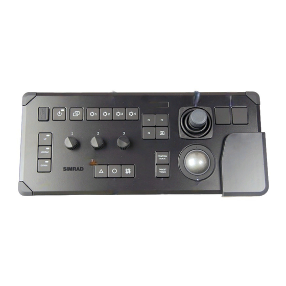
• Before you turn on the CS90, make sure that you have sufficient water depth to lower the transducer! • You must never turn on the CS90 when the ship is in dry dock. The transducer may be damaged if it transmits in open air. - Page 20 Button Options assign one function to each button on the Operating Panel. : Press this button to make a copy of the current CS90 presentation. Screen Capture You can choose either a single screen capture or a sequence with multiple screen captures.
- Page 21 Trackball Note The CS90 supports two different operating panels. These are referred to as "Mk1" and "Mk2". In this publication all descriptions and references are related to "Mk2". Before you can change the settings related to a view, you must click inside the view to activate it.
-
Page 22: Starting Normal Operation
Turning off the CS90, page 35 Turning on the CS90 for normal use In order to use the CS90, you must first turn it on. To turn on the CS90 use the Power button on the Operating Panel. The CS90 program starts automatically when the Processor Unit is turned on. -
Page 23: Getting To Know The User Interface
Main Operation The icon is flashing to indicate that even if the CS90 is turned on, "pinging" is disabled. The CS90 is in Normal mode, but is set to Off to prevent TX Power transmissions. - Page 24 Move the cursor to the top bar, and investigate the functions provided. The CS90 top bar is located at the top of the display presentation and stretches from the far left to the far right. The top bar gives you fast access to key functionality and navigational information.
-
Page 25: Getting To Know Presentation Modes And Views
Context The CS90 presents the echo data in different views. All information from each ping is shown in all the views simultaneously. Each view uses its individual transmit frequency, and you set up the different views with different operating parameters. The behaviour of the echoes in each view is controlled by your course and speed combined with the movements of the target(s). - Page 26 Simrad CS90 Operator Manual With the various beams provided by the CS90, it may be difficult to understand the concept. How do these beams "behave" in the water? By means of a graphic presentation, the dialog box attempts to give you a better Beam Visualization understanding of how the acoustic beams are transmitted into the water.
- Page 27 Cosmetics At the bottom of the CS90 presentation, select a suitable presentation mode, and activate the 270 Vertical view. The 270 Vertical view is designed for purse seining. The view combines a horizontal "bow up"...
- Page 28 If you have connected a compatible catch monitoring system to your CS90, information from these sensors are shown in the Catch view. At the bottom of the CS90 presentation, select a suitable presentation mode, and activate the Echogram view. The Echogram view provides echo data from a horizontal beam in a common echogram presentation.
-
Page 29: Selecting Normal Mode To Start "Pinging
Related topics Starting normal operation, page 20 Selecting Normal mode to start "pinging" In order to transmit ("ping") you must set the CS90 to Normal operating mode. This is the default mode when the CS90 is turned on. Context function controls the operating mode of the CS90. You can set it to Operation Normal, Replay or Inactive. -
Page 30: Adjusting The Radius Of The Search Area
Adjusting the radius of the search area Some echoes are close, others are further away. It is often necessary to adjust the radius of the search area. On the CS90, this is referred to as range. Context setting defines how "far" you wish the CS90 to detect echoes. In other... -
Page 31: Adjusting The Echo Sensitivity
Starting normal operation, page 20 Adjusting the echo sensitivity Some echoes are weak while others are stronger. To compensate for this it is often necessary to adjust the sensitivity of the CS90. This adjustment is commonly referred to as gain. Context You can compare this gain setting with the volume control on your car radio. - Page 32 Simrad CS90 Operator Manual see. However, since you also increase the acoustic noise in the reception, the CS90 presentations will also show this noise. Too much gain may therefore "distort" the presentation. Comparing the gain function with the volume control on your car radio is not very accurate.
-
Page 33: Changing The Vertical Angle Of The Sonar Beams
Getting started Optionally: Observe the menu. Main Its default location is on the right side of the CS90 presentation. Select Gain Make the necessary adjustment. Select [+] or [-] to choose the requested setting. Place the cursor on the button. Press and hold the left mouse button. Move the cursor horizontally over the button. - Page 34 Once again you can activate the RCG function to improve the reading. With the various beams provided by the CS90, it may be difficult to understand the concept. How do these beams "behave" in the water? By means of a graphic...
-
Page 35: Adjusting The Horizontal Direction Of The Sonar Beam
Related topics Starting normal operation, page 20 Adjusting the horizontal direction of the sonar beam The Horizontal view in the CS90 presentation covers the entire Omni sector For the other views you must define the horizontal direction of the beam. Context In the Horizontal view the current bearing is shown with a continuous line pointing out from the vessel position. - Page 36 In a Horizontal view, select the bearing line and drag it sideways. Optionally: Observe the menu. Main Its default location is on the right side of the CS90 presentation. Select Bearing Make the necessary adjustment. Select [+] or [-] to choose the requested setting.
-
Page 37: Turning Off The Cs90
Power Off Power on the Operating Panel. You must never turn off the CS90 by means of the on/off switch on the Processor Unit. Context When you do not use the CS90, turn off the display and the Processor Unit. -
Page 38: Basic Operating Procedures
With a few exceptions, the chosen language will also be used for all other text on the CS90. The CS90 help may not be available for the language you choose. If your language is not supported, the English help is provided. -
Page 39: Selecting Operating Frequency For Minimum Noise
We recommend that you do this test twice. First, do the test with all other hydroacoustic systems (echo sounders, ADCP, sonars) turned off. Second, do the test with normal operating conditions. This allows you to see how the other hydroacoustic systems affect the CS90 operation. Procedure On the... -
Page 40: Hiding The Menu System When You Do Not Need It
CS90 presentation. This gives you more space for echo information. Context The menu system is by default located on the right side of the CS90 presentation. The menus are organized in a tree structure with a main menu, a set of secondary menus, and several menu buttons. - Page 41 Getting started on the top bar allows you to make a copy of the current CS90 Screen Capture presentation. You can also use the button on the Operating Panel. Screen Capture Procedure Choosing screen capture mode: Open the menu. Setup...
-
Page 42: Saving The Current User Settings
Simrad CS90 Operator Manual Saving the current user settings When you have spent some time working with the CS90, you are probably using specific settings that you know are efficient for your purpose. It is a good idea to save these settings. -
Page 43: Defining The Ping (Transmission) Modes
Specify the interval between each ping. Select either side of the button to choose a value. Select the middle of the button to open it. If you have a keyboard connected to the CS90, you can type the requested value. -
Page 44: Related Topics
Simrad CS90 Operator Manual to Single Ping. Transmission Mode The CS90 transmits (pings) only when you select the symbol on the right side of the button. Related topics Basic operating procedures, page 36 457423/A... -
Page 45: Operating Procedures
Operating procedures Operating procedures Topics Getting started, page 44 Choosing operating mode and key transmit parameters, page 48 Controlling the gain and range settings, page 56 Using the markers and tracking features, page 64 Improving the recognition of fish and schools using receiver filters, page 72 Recording and replaying echo data, page 80 Setting up presentation modes and views, page 86 Defining settings related to user preferences and individual customizing, page 89... -
Page 46: Getting Started
Turning off the CS90, page 46 Turning on the CS90 In order to use the CS90, you must first turn it on. To turn on the CS90 use the Power button on the Operating Panel. The CS90 program starts automatically when the Processor Unit is turned on. -
Page 47: Lowering And Hoisting The Transducer From The User Interface
Main Operation The icon is flashing to indicate that even if the CS90 is turned on, "pinging" is disabled. The CS90 is in Normal mode, but is set to Off to prevent TX Power transmissions. -
Page 48: Turning Off The Cs90
Turning off the CS90, page 46 Turning off the CS90 When you do not use the CS90, turn off the entire system. To power down the three Power Supply Units and the Transceiver Unit, use the functionality in the CS90 program. - Page 49 Operating procedures Related topics Getting started, page 44 Turning on the CS90, page 44 Lowering and hoisting the transducer from the user interface, page 45 457423/A...
-
Page 50: Choosing Operating Mode And Key Transmit Parameters
Adjusting the output power to match varying conditions, page 53 Selecting the best operating frequency, page 54 Selecting Normal mode to start "pinging" In order to transmit ("ping") you must set the CS90 to Normal operating mode. This is the default mode when the CS90 is turned on. Context function controls the operating mode of the CS90. -
Page 51: Selecting Replay Mode
Selecting Replay mode, page 49 Selecting Inactive mode, page 50 Selecting Replay mode Replay mode allows you to play back previously recorded raw data. The CS90 can not operate normally while in Replay mode. Neither transmission nor reception takes place. Context All playback is controlled by the replay bar. -
Page 52: Selecting Inactive Mode
Normal, Replay or Inactive. Note Note that Inactive operating mode is not the same as Passive mode. While Inactive mode stops both transmission and reception, Passive mode will still allow the CS90 to receive echoes. To select passive mode set to Normal and to Off. -
Page 53: Setting Up The Cs90 For Maximum Echo Refresh Rate
Selecting Normal mode to start "pinging", page 48 Selecting Replay mode, page 49 Setting up the CS90 for maximum echo refresh rate You can set up the CS90 to transmit (ping) as often as possible. This gives you the maximum refresh rate. Context... -
Page 54: Transmitting Single Pings
Simrad CS90 Operator Manual Transmitting single pings You can set up the CS90 to transmit a single ping only when you select the Transmission button. Mode Context to control how often the CS90 Transmission Mode shall transmit its energy into the water. For normal use, choose Maximum. -
Page 55: Adjusting The Output Power To Match Varying Conditions
Select either side of the button to choose a value. Select the middle of the button to open it. If you have a keyboard connected to the CS90, you can type the requested value. You can also change the value by selecting - and holding - the middle of the button, and move the cursor sideways. -
Page 56: Selecting The Best Operating Frequency
Some of our users claim that reducing the output may be useful if you are looking for scattered fish. If you operate in the close vicinity of other vessels that are also using the CS90, interference may cause problems. Reducing the output power is not a practical way to deal with interference. - Page 57 We recommend that you do this test twice. First, do the test with all other hydroacoustic systems (echo sounders, ADCP, sonars) turned off. Second, do the test with normal operating conditions. This allows you to see how the other hydroacoustic systems affect the CS90 operation. Procedure On the...
-
Page 58: Controlling The Gain And Range Settings
Weak echoes will be easier to see. However, since you also increase the acoustic noise in the reception, the CS90 presentations will also show this noise. Too much gain may therefore "distort" the presentation. - Page 59 Operating procedures reduces the minimum level, and this increases the sensitivity. Only echoes over the minimum level are shown in the echogram (C). Do not confuse this setting with the (Time Varied Gain) setting. Gain During normal operating conditions we recommend that you keep the gain between 15 and 30.
-
Page 60: Adjusting The Tvg (Time Variable Gain) Setting
Context The TVG (Time Varible Gain) compensation is designed to counteract the natural phenomena of geometric spread and absorption loss. In the CS90, the TVG compensation is made using digital signal processing software. The TVG compensation is expressed as a logarithmic curve. Each curve has a different slope creating a different gain compensation. - Page 61 Operating procedures Note The range value selected and shown is by default only used by the active view. Even though you can choose a large range value, that does not mean that you can detect your targets on the same range. The range value only defines the range that is shown in the views.
-
Page 62: Adjusting The Intensity Of The Echo Presentations
(Automatic Gain Control). The is applied Display Gain towards the end of the filter sequence in the CS90. This means that you can use if you are not completely satisfied with the results of the automatic gain Display Gain functionality. - Page 63 Once again you can activate the RCG function to improve the reading. With the various beams provided by the CS90, it may be difficult to understand the concept. How do these beams "behave" in the water? By means of a graphic...
-
Page 64: Adjusting The Bearing
Related topics Controlling the gain and range settings, page 56 Adjusting the bearing The Horizontal view in the CS90 presentation covers the entire Omni sector For the other views you must define the horizontal direction of the beam. Context In the Horizontal view the current bearing is shown with a continuous line pointing out from the vessel position. - Page 65 Operating procedures Procedure Click in the view you want to activate. The active view is identified with a thicker border. Unless you use the Apply to all function, all changes you make will only be applied to this view. Turn the relevant rotary switch to make the adjustment. The Operating Panel is fitted with three rotary switches.
-
Page 66: Using The Markers And Tracking Features
Choosing the fishing gear in use, page 70 Changing the fishing gear properties to match your own equipment, page 71 Starting a position track A position track permits the CS90 to automatically control the tilt and bearing based on the movements of your vessel. Context The position track locks on a position defined by its latitude, longitude and depth. -
Page 67: Starting A Target Track
Result The marker is shown as a small triangle with or without a short identifying label. Once an echo has bee provided with a marker in the CS90 presentation it is regarded as an object. Note If you change the tilt and bearing settings manually, the position track is disabled. If you create a new marker and give this priority, the position track is disabled. -
Page 68: Placing A New Marker
Simrad CS90 Operator Manual A new tracked object is automatically given priority status. The priority is identified with a "P". Only one single object can be given priority status. If you start tracking a new target the first target will loose its priority. The same applies if you give priority to another marker. -
Page 69: Deleting A Marker
Press on the Operating Panel. Marker Result Once an echo has bee provided with a marker in the CS90 presentation it is regarded as an object. The menu provides a list of all current objects. This includes Objects all types of objects including those classified as targets. -
Page 70: Measuring The Size Of A School Relative To The Purse Seine
Estimating the size of a school can sometimes be challenging. A single circle marker can be placed in the CS90 presentation. The circle is drawn with the same diameter as your purse. By means of the circle you can see the size of the school relative to your purse. - Page 71 The history line shows the movements of your vessel. Since the CS90 knows the length of your net, it places a second marker on this line when half the length has been spent. When the entire net has been spent, a third rectangular marker is shown.
-
Page 72: Choosing The Fishing Gear In Use
Changing the fishing gear properties to match your own equipment, page 71 Choosing the fishing gear in use By defining the type of fishing gear you are using, the CS90 may provide more accurate visual presentations. The function allows you to define the size of your Fishing Gear trawl or purse seine. -
Page 73: Changing The Fishing Gear Properties To Match Your Own Equipment
Operating procedures Changing the fishing gear properties to match your own equipment Use the dialog box to change the fishing gear properties to match Fishing Gear Setup your own equipment. Context Accurate fishing gear properties are important for the following functionality: •... -
Page 74: Improving The Recognition Of Fish And Schools Using Receiver Filters
Adjusting the intensity of the echo presentations, page 79 About the receiver filter sequence in the CS90 The filters in the CS90 are implemented in “series”. Any changes to a filter setting may therefore have an effect on subsequent filters. -
Page 75: Reducing Noise And Reverberation With The Agc (Automatic Gain Control) Function
When sonar conditions are poor, effective tuning of the filters in the CS90 may be necessary to achieve a satisfactory result. Automatic Gain Control (AGC) is one of the tools provided by the CS90 to remove noise and reverberation from the echo presentation. -
Page 76: Reducing Propeller Noise And Interference With The Noise Filter
Use weak filtering - or turn the filter off - if you have strong echoes on short ranges. The filter may then be too powerful, and distort the echo presentation. The filters in the CS90 are implemented in “series”. The noise filtering is done in two stages early in the receiver process. -
Page 77: Reducing Bottom And Surface Reverberation With The Rcg (Reverberation Controlled Gain) Function
Operating procedures Open the menu. Active Select Noise Filter Select a value from the options provided. The choice you make is by default only applied to the currently selected (active) view. Related topics Improving the recognition of fish and schools using receiver filters, page 72 Reducing bottom and surface reverberation with the RCG (Reverberation Controlled Gain) function When you transmit an acoustic pulse into the water to search for a target, echoes will... - Page 78 Use for scattered fish. This setting uses a slightly different algorithm than the other scattered fish settings. The filters in the CS90 are implemented in “series”. The reverberation controlled gain adjustment is made late in the sequence, so any changes to the preceding filters may have an effect on how it works.
-
Page 79: Reducing Noise And False Echoes With The Ping-Ping Filter
Reducing noise and false echoes with the Ping-Ping Filter analyses the historical information from previous consecutive pings Ping-Ping Filter in order to remove unwanted noise and false echoes from the CS90 presentation. Context The following filter options are provided. •... -
Page 80: Reducing Noise And Reverberation With The Agc (Automatic Gain Control) Function
When sonar conditions are poor, effective tuning of the filters in the CS90 may be necessary to achieve a satisfactory result. Automatic Gain Control (AGC) is one of the tools provided by the CS90 to remove noise and reverberation from the echo presentation. -
Page 81: Adjusting The Intensity Of The Echo Presentations
(Automatic Gain Control). The is applied Display Gain towards the end of the filter sequence in the CS90. This means that you can use if you are not completely satisfied with the results of the automatic gain Display Gain functionality. -
Page 82: Recording And Replaying Echo Data
Defining the file and folder settings for data recording A useful function of the CS90 is it ability to record echo data. You can save the data to the Processor Unit hard disk, or onto an external storage device. To retrieve the data files you need to know where they are, and which file names that have been used. -
Page 83: Recording Echo Data
The data files will normally become very large. If you wish to record large amounts of CS90 data, make sure that you have enough space on your hard disk. The CS90 is not provided with unlimited disk capacity. We recommend that you save the data files to an external storage device. -
Page 84: Selecting Replay Mode
Related topics Recording and replaying echo data, page 80 Selecting Replay mode Replay mode allows you to play back previously recorded raw data. The CS90 can not operate normally while in Replay mode. Neither transmission nor reception takes place. Context All playback is controlled by the replay bar. -
Page 85: Choosing Which Echo Data File(S) To Replay
Operating procedures to Replay. Operation The replay bar opens automatically. It is positioned directly below the top bar at the top of the CS90 presentation. If you need to select which files to replay, select under the Replay File Operation button. -
Page 86: Accessing The Echo Data Files To Delete, Move Or Copy Them
Accessing the echo data files to delete, move or copy them Use the data recording functionality provided by the CS90 to save echo data. You can save the data to the Processor Unit hard disk, or onto an external storage device. - Page 87 Operating procedures In the file manager utility, locate the folder you defined in the dialog box. File Setup Use the functionality provided by the operating system to delete the files, or to copy or move them to the storage device. Close the file manager utility.
-
Page 88: Setting Up Presentation Modes And Views
Unit you can even move selected views to another display. With the Docking Views function you can move and re-size the views in the CS90 presentation. Context The physical location and size of each view can be changed individually. The content in a view that changes size will automatically be adjusted to take full advantage of the space available. -
Page 89: Rearranging The Layout Of The Cs90 Presentation
We recommend that you first save your current user settings. When a complete reorganisation of the view positions and sizes have been completed , you may wish to restore the CS90 presentation to what it was before you changed it. You must use the dialog box to do this. -
Page 90: Restoring The Locations And Sizes Of The Views
CS90 Docking Views presentation. When a complete reorganisation of the view positions and sizes have been completed , you may wish to restore the CS90 presentation to what it was before you changed it. Procedure... -
Page 91: Defining Settings Related To User Preferences And Individual Customizing
With a few exceptions, the chosen language will also be used for all other text on the CS90. The CS90 help may not be available for the language you choose. If your language is not supported, the English help is provided. -
Page 92: Hiding The Menu System
CS90 presentation. This gives you more space for echo information. Context The menu system is by default located on the right side of the CS90 presentation. The menus are organized in a tree structure with a main menu, a set of secondary menus, and several menu buttons. -
Page 93: Placing The Menu On The Left Side Of The Cs90 Presentation
"on/off switches". Some of these "on/off switches" General are used to enable or disable the information shown on the top bar. Note The information shown on the CS90 top bar must not be used for vessel navigation. Procedure Open the menu. -
Page 94: Enabling Coordinated Universal Time (Utc) On The Bottom Bar
ZDA datagram. The NMEA ZDA datagram contains the universal time code (UTC), day, month, year and local time zone. Context This is an "on/off" switch. The time is shown on the bottom bar of the CS90 presentation. Procedure Open the menu. -
Page 95: Adjusting The Backlight Intensity On The Operating Panel
Select the right side of the button to increase the value. Select the middle of the button to open it.If you have a keyboard connected to the CS90, you can type the requested value. Related topics... -
Page 96: Reducing The Light Emitted From The Display Presentation
Simrad CS90 Operator Manual Reducing the light emitted from the display presentation When the bridge is dark, the light emitted by the CS90 display can affect your night vision. In order to compensate for this, you can reduce the intensity Context The intensity of the light given off by the CS90 presentation can be adjusted. -
Page 97: Changing The Colour Palette ("Skin") Used In The Cs90 Presentations
Defining settings related to user preferences and individual customizing, page 89 Changing the colour palette ("skin") used in the CS90 presentations Depending on the ambient light, it is possible to change the CS90 presentation colours to help you see the information. The function allows you to choose which colour Palette theme ("skin") to be used by the CS90. -
Page 98: Choosing The Colours Used To Present The Echoes
This implies that the next colour is selected every time the echo strength is doubled. If you choose to use many colours, the resolution of the CS90 presentation is greatly improved. It is then easier to distinguish the difference between the various echoes of different size and/or target strength. -
Page 99: Configuring The Environmental Parameters
Operating procedures Note When you work in the dialog box, you must always select to save the Installation Apply changes made on a page. You must do this before you continue working on a different page. Procedure Open the menu. Setup On the menu, select... -
Page 100: Setting Up The Alarm Limits For System Protection
Defining settings related to user preferences and individual customizing, page 89 Setting up the alarm limits for system protection Safe operation of the CS90 is made possible using multiple sensors that monitor the operation and the performance. Whenever a suspicious event takes place, a relevant message, warning or alarm is provided. -
Page 101: Defining The Middle Position Of The Transducer
The hull unit provided with the CS90 is designed to lower the transducer down below the ship’s hull when the CS90 shall be used. When the CS90 is switched off, the transducer is hoisted for protection. The CS90 allows you to define a middle position for the transducer. - Page 102 Installation Lower the transducer to its middle position. Start normal operation. Make sure that the CS90 operates normally without transmitting into the installation trunk. Related topics Defining settings related to user preferences and individual customizing, page 89 457423/A...
-
Page 103: Saving, Retrieving And Handling User Settings
Choosing CS90 factory default settings, page 105 Saving the current user settings When you have spent some time working with the CS90, you are probably using specific settings that you know are efficient for your purpose. It is a good idea to save these settings. -
Page 104: Choosing Previously Saved User Settings
Choosing previously saved user settings User settings that either you or any of your colleagues have saved can easily be retrieved and put to use. This shortens down the time it takes to get started with the CS90. Context dialog box is used to store your favourite CS90 settings. These settings... -
Page 105: Renaming Existing User Settings
You can use different settings to create as many user profiles as you like, and give them any name. All the settings you have chosen using functions and dialog boxes in the CS90 user interface are saved. To rename a user setting, select its name in the list, and then select . -
Page 106: Deleting User Settings That Are No Longer Used
You can use different settings to create as many user profiles as you like, and give them any name. All the settings you have chosen using functions and dialog boxes in the CS90 user interface are saved. To delete a user setting, select its name in the list, and then select . -
Page 107: Choosing Cs90 Factory Default Settings
Choosing CS90 factory default settings Sometimes it may be useful to reset the CS90 to work with a set of known user settings. A set of "factory settings" is provided for this purpose. The settings may be put to use if you are uncertain of which values to use. -
Page 108: Defining The User-Selected Features On The Operating Panel
Operating Panel and the menu system shown in the CS90 presentation. You can also use a standard computer mouse to control the CS90. The mouse can be connected to either the Operating Panel or directly to the Processor Unit. -
Page 109: Assigning Custom User Settings To The Operating Panel
Defining the user-selected features on the Operating Panel, page 106 Assigning custom user settings to the Operating Panel dialog box is used to store your favourite CS90 settings. These settings User Settings can be related to different operations, environmental conditions or basic personal preferences. - Page 110 Simrad CS90 Operator Manual page is used to select which physical hardware panel you use on Operating Panel your CS90, and to assign functionality to the programmable buttons. This page is located in the dialog box. The dialog box is located on the menu.
-
Page 111: Assigning Functions To The Rotary Switches On The Operating Panel
Installation Setup Note The CS90 supports two different operating panels. These are referred to as "Mk1" and "Mk2". In this publication all descriptions and references are related to "Mk2". Procedure Open the menu. -
Page 112: Assigning Functions To F1, F2 And F3 On The Operating Panel
. Each button can be assigned a dedicated function. Context page is used to select which Operating Panel physical hardware panel you use on your CS90, and to assign functionality to the programmable buttons. This page is located in the dialog box. The... - Page 113 Place Own Ship Marker menu. Select this function to add a square symbol to the vessel’s current position in the CS90 presentation. The own ship marker is now regarded as an object. All information about the object is shown in the menu listed as "OSM".
-
Page 114: Lowering And Hoisting The Transducer From The Sonar Room
Simrad CS90 Operator Manual Lowering and hoisting the transducer from the sonar room Topics Lowering and hoisting the transducer using the Hoist/Lower Switch, page 113 Lowering and hoisting the transducer using the hand crank, page 115 Emergency lowering and hoisting using the two contactors, page 117... -
Page 115: Lowering And Hoisting The Transducer Using The Hoist/Lower Switch
Operating procedures Lowering and hoisting the transducer using the Hoist/Lower Switch The Operating Panel controls the lowering and hoisting of the transducer. Dedicated buttons are provided for the physical transducer locations. You can also do this from the Motor Control Unit. Local control is useful for maintenance purposes. Prerequisites You need a suitable screwdriver or a large coin to open the... - Page 116 Simrad CS90 Operator Manual Set the switch to position LOWER. Lowering is automatically stopped when the is activated. Lower Limit Switch If necessary, the transducer can be stopped in any position by setting the to STOP. Hoist/Lower Switch Set the switch to position STOP.
-
Page 117: Lowering And Hoisting The Transducer Using The Hand Crank
Operating procedures Lowering and hoisting the transducer using the hand crank The Operating Panel controls the lowering and hoisting of the transducer. In case of a power failure the transducer can be hoisted or lowered manually by means of a hand crank. - Page 118 Simrad CS90 Operator Manual Remove the hand crank from its storage position. Remove the plastic plug on the top cover of the hull unit. Mount the hand crank onto the stub shaft through the hole in the top cover. Locate the brake release screw on the motor.
-
Page 119: Emergency Lowering And Hoisting Using The Two Contactors
Operating procedures Emergency lowering and hoisting using the two contactors In case of emergency it is possible to bypass the control logic in the Motor Control Unit. You can control the hoisting motor directly using the two designated contactors. Prerequisites You need a suitable screwdriver or a large coin to open the Motor Control Unit cabinet. - Page 120 Simrad CS90 Operator Manual Open the cabinet door. WARNING High voltages are used. This equipment must be serviced only by qualified personnel familiar with high-voltage equipment and the potential hazards involved. Failure to observe this precaution could result in bodily injury.
-
Page 121: Setting Up The Interfaces To Peripheral Devices
Installation Sensor Configuration so that the information from the "most reliable" sensor is used by the CS90. You can also define manual values in case a sensor is unserviceable, or not installed. Prerequisites The new sensor is physically connected to the CS90 using a serial or network cable. -
Page 122: Defining The Serial And Ethernet (Lan) Port Parameters
Defining the serial and Ethernet (LAN) port parameters For any sensor interface to work, the communication parameters must be set up correctly. The CS90 software automatically scans the Processor Unit to locate and identify the available communication ports. Once the software has established a list of valid interfaces, you can set up and control the communication parameters. - Page 123 Operating procedures • The communication parameters required for the sensor interface are known. Context page provides two lists; one for serial ports and one for Ethernet I/O Setup (LAN) ports. Each list is supported with a set of functions to set up and monitor the communication ports.
-
Page 124: Setting Up The Input From A Navigation System (Gps)
• The interface port is set up with the correct communication parameters. • The CS90 system is turned on and operates normally. • The new sensor is physically connected to the CS90 using a serial or network cable. It is switched on and in normal operation. - Page 125 You cannot make any changes here. To change the communication parameters, use the page. I/O Setup If you want to check that the peripheral system is transmitting data to the CS90, select Monitor dialog box provides one text box for incoming messages (...
-
Page 126: Setting Up The Interface For Speed Log Input
• The interface port is set up with the correct communication parameters. • The CS90 system is turned on and operates normally. • The new sensor is physically connected to the CS90 using a serial or network cable. It is switched on and in normal operation. - Page 127 You must specify which communication port to use (LAN (Local Area Network) or serial port). You can type a custom name to identify the sensor import. In the list of valid datagram formats, select the format(s) to be accepted by the CS90. Note Just making changes and selecting at the bottom of the page will not install anything.
-
Page 128: Setting Up The Interface For Course Gyro Input
Setting up the interfaces to peripheral devices, page 119 Setting up the interface for course gyro input In order to operate correctly, the CS90 requires input from a course gyro. In most cases a suitable course gyro is already installed on the vessel. A global positioning system (GPS) with a compatible output format can also be used. - Page 129 Operating procedures • The new sensor is physically connected to the CS90 using a serial or network cable. It is switched on and in normal operation. Neither tools nor instruments are required. Context Note The input from a course gyro is essential for CS90 operation. Without the input from a course gyro, the CS90 will not be able to present correct navigational information.This...
- Page 130 Simrad CS90 Operator Manual If you want to check that the peripheral system is transmitting data to the CS90, select Monitor dialog box provides one text box for incoming messages ( Port Monitor ), and one for outgoing messages ( ).
-
Page 131: Configuring The Sensor Interface
Prerequisites This procedure assumes that: • The new sensor is physically connected to the CS90 using a serial or network cable. • The interface port is set up with the correct communication parameters. • The navigation sensor is installed into the CS90 software. The relevant interface parameters and physical location properties are defined. -
Page 132: Setting Up The Input From A Motion Reference Unit (Mru)
• The interface port is set up with the correct communication parameters. • The CS90 system is turned on and operates normally. • The new sensor is physically connected to the CS90 using a serial or network cable. It is switched on and in normal operation. - Page 133 Operating procedures Context A motion reference unit (MRU) measures the vessel’s pitch and roll movements in the sea. The information provided by the motion sensor is used by the CS90 to stabilize the beams and the echo presentation. Note This task is only applicable is you are using an external motion reference unit on your CS90.
-
Page 134: Setting Up The Cs90 In A Synchronized System
Setting up the CS90 in a synchronized system If you want to use the CS90 as a master or slave in a synchronized system, you must set it up for such operation. To do this, you must select which communication port to use for the synchronization interface, and you must select the requested synchronization mode. - Page 135 • Master Master mode is used if the CS90 is going to act as the controlling unit in a synchronized system. The peripheral hydroacoustic system(s) are only permitted to transmit when enabled by the CS90. When Master mode is selected, the CS90 will run using its internal ping interval parameters and send trigger signals to the peripheral system(s).
- Page 136 This delay will only work when the synchronization is set up using a serial port. • Slave In Slave mode, the CS90 waits for the delay time after the external trigger signal has arrived before transmitting the ping. This is often referred to as a post-trigger. From the list of ports available, select...
-
Page 137: Menu System
Menu system Menu system Topics About the menus and menu buttons, page 136 Using the “smart” menu buttons, page 136 Main menu, page 139 Operation menu, page 141 Display menu, page 143 Setup menu, page 146 Active menu, page 150 Objects menu, page 153 Visual Objects menu, page 157 Cosmetics menu, page 160... -
Page 138: About The Menus And Menu Buttons
When the menu is hidden, it is temporarily Menu shown on the left or right side of the CS90 presentation if you move the cursor to that position. Using the “smart” menu buttons Each menu provided by the CS90 contains several menu buttons. - Page 139 • Spin the scroll wheel in either direction to increase or decrease the numerical value. • Type a numerical value. (You can only type a new value if a computer keyboard is connected to your CS90 Processor Unit.) • Select the button to open the button menu. Choose the required setting.
- Page 140 Simrad CS90 Operator Manual Choosing a setting on the button menu Place the cursor on the button. Select the button to open the button menu. Choose the required setting., The chosen setting is applied, and the menu closes automatically. Several of the functions offer .
-
Page 141: Main Menu
It offers the most common Main functions for efficient use of the CS90. Unless you hide the entire menu system, the Main menu is visible at all times, even if you close the secondary menus. - Page 142 Simrad CS90 Operator Manual • Bearing The Horizontal view in the CS90 presentation covers the entire Omni sector For the other views you must define the horizontal direction of the beam. Use Bearing adjust the horizontal angle referenced to the vessel heading.
-
Page 143: Operation Menu
Immediately after you have turned on the CS90, the icon is flashing. The icon Operation is flashing to indicate that even if the CS90 is turned on, "pinging" is disabled. When the CS90 is turned on, is by default set to Off. This is a safety precautions to Tx Power prevent inadvertent transmissions when the vessel is in dry dock. - Page 144 Simrad CS90 Operator Manual • Tx Power to increase or decrease the output power. The output power is selected Tx Power from predefined steps. 457423/A...
-
Page 145: Display Menu
The choices in the this menu depends on which view in the CS90 presentation that is currently "active". The menu may therefore change from one view to another. The screen capture may not show you all the menu choices. - Page 146 View Range the original value. This function can be used if you wish to move your ship Range symbol to the bottom of the CS90 view. You can then expand the range without adding zoom. • Display Gain increases or decreases the strength of the echo presentation.
- Page 147 CS90 presentation. • About Every CS90 software release is uniquely identified. The dialog box identifies About the current CS90 software version with its release date. The version described in this Operator Manual is 3.1.4. 457423/A...
-
Page 148: Setup Menu
An invisible area - the tracking area - is created as an acquisition area. In order for the CS90 to find and lock on the intended target, it needs to be kept within this tracking area. If the intended target falls outside the area, the tracking can not be started. - Page 149 Depending on the current sea and weather conditions, you may need to change these values frequently. • Language You may prefer to use the CS90 with a user interface in your own language. A selection of languages is provided. The function allows you to select the Language language to be used in the CS90 presentations, menus and dialog boxes.
- Page 150 • Installation Before you use the CS90 you must set it up to communicate with the relevant peripherals. This includes the transducer. Use the dialog box to set up all...
- Page 151 – Hull Unit Configuration A choice of hull units is available for the CS90 Fish Finding Sonar. The hull units offer different physical properties and lowering depths. The hull unit must always be enabled. If you disable the hull unit, all hull unit functionality will be removed from the CS90.
-
Page 152: Active Menu
The choices in the this menu depends on which view in the CS90 presentation that is currently "active". The menu may therefore change from one view to another. The name of the currently active view is identified at the top of the menu. - Page 153 • Ping-Ping Filter analyses the historical information from previous consecutive Ping-Ping Filter pings in order to remove unwanted noise and false echoes from the CS90 presentation. • Pulse Type function allows you to select the "shape" of the transmitted pulses Pulse Type ("pings").
- Page 154 Simrad CS90 Operator Manual • Bottom Filter Threshold The CS90 provides a bottom filter to reduce the sometimes powerful echo from the seabed. This filter is useful if you try to find fish close to the bottom. Select a Bottom value to control the "strength"...
-
Page 155: Objects Menu
- in spite of its name and location - not a menu at all. This "menu" Objects opens a small view to monitor and control the objects you have defined in the CS90 presentation. Each object is identified with a visual marker. - Page 156 Delete Select to delete all the markers you have selected in the objects list. Each Delete marker is removed both from the list and from the CS90 presentation. Select to add a new marker manually. The dialog box opens to New Marker accept position and depth information.
- Page 157 Menu system Control buttons In the object list, select the object line to activate the control buttons for that particular object. Priority One marker can be given priority status to identify the object as the most important target or position. Select to give the currently Priority...
- Page 158 Simrad CS90 Operator Manual Comment A text field at the bottom of the menu allows you to type comments. You Objects can only do this if you have computer keyboard connected to your Processor Unit. Insert Relative Position Select to insert object information into the comment field.
-
Page 159: Visual Objects Menu
The choices in the this menu depends on which view in the CS90 presentation that is currently "active". The menu may therefore change from one view to another. The screen capture may not show you all the menu choices. - Page 160 Minute Markers In order to maintain a visual presentation of your vessel’s previous movements, you can draw these with a line. This line is drawn after the vessel symbol in the CS90 presentation, and visualizes your past movements. The function adds Minute Markers markers to the line to indicate the travelled distance for each minute.
- Page 161 The length of the line reflects its speed. For this function to work, a sea current meter must be connected to the CS90. The use of an ADCP (Acoustic Doppler Current Profiler) is recommended.
-
Page 162: Cosmetics Menu
The choices in the this menu depends on which view in the CS90 presentation that is currently "active". The menu may therefore change from one view to another. The screen capture may not show you all the menu choices. - Page 163 Menu system • (Variable Range Ring Range) VRR Range You can use to manually define a range for the variable range ring. VRR Range • Compass Cards Activate to place evenly spaced compass markers on the outer range Compass Cards ring in horizontal views.
-
Page 164: Shortcut Menus
The screen capture is provided as an example. In this context, the phrase marker is used to identify a visual symbol placed in the CS90 presentation. By placing a marker on the echo it is regarded as an object that you can act upon. - Page 165 Place Own Ship Marker in the CS90 presentation. The own ship marker is now regarded as an object. All information about the object is shown in the menu listed as "OSM".
- Page 166 Simrad CS90 Operator Manual • Place Ruler Place the cursor over the first echo. Right-click to open the shortcut menu, then select . The ruler starts wherever you place the cursor, and ends when you Place Ruler release the button. The length and relative bearing of the ruler is displayed next to it.
- Page 167 7 changing........... 95 online information ........7 colours purpose of this manual ........7 choosing colour brightness ......96 registered trademark SIMRAD ......7 choosing colour scale........96 registered trademarks........7 choosing echo colours........96 software version........... 7 comments suggestions ..........
- Page 168 Simrad CS90 Operator Manual description ..........163 Docking Views Delete Ruler function restoring original views ......... 88 description ..........164 restoring previous views ........ 88 deleting documents existing user settings ........104 download from website ........7 description download Bottom Profile function ....... 157 documents from website .........
- Page 169 Index Bottom Profile function description ....157 high voltage Bow Marker function description ....159 safety rules..........13 Current Vector function description ....159 hoist Delete All Rulers function description....164 transducer manually ........9 Delete Marker function description ....163 Hoist/Lower Switch Delete Own Ship Marker function hoisting the transducer ........
- Page 170 Simrad CS90 Operator Manual lower the transducer using hand crank....115 defining the middle position of the lower the transducer using Hoist/Lower transducer..........99 Switch..........113 lower the transducer using Lowering Contactor ..........117 measure the size of a school relative to the I/O Setup page purse seine..........
- Page 171 Index K302 Setup menu description ....... 146 lowering the transducer ....... 117 Visual Objects menu description ....157 Kongsberg Maritime menu buttons support ............ 13 using ............. 136 menu language select..........36, 89 menu system description ..........136 LAN port hiding ............
- Page 172 Simrad CS90 Operator Manual information ..........7 playback file open selecting ........... 83 Active menu ..........150 Position Object Sizes Cosmetics menu........160 description ..........157 Display menu........... 143 power off Main menu..........139 important reminder ........9 Objects menu ........... 153 power up Operation menu ........
- Page 173 Index increasing the visibility of the information Operating Panel .......... 17 panes ............. 94 this manual..........7 installing navigation and other sensors (summary) ..........119 lowering the transducer from the sonar room........113, 115, 117 range lowering the transducer using hand crank ..115 adjusting ..........
- Page 174 Simrad CS90 Operator Manual changing environmental parameters....97 saving the current user settings ....40, 101 salt water using previously saved user settings ....102 changing environmental parameters....97 setup save select menu language....... 36, 89 screen capture ..........38 Setup menu sequential screen captures ......
- Page 175 ........7 transducer handling when not in use important rules ..........9 important reminder ........8 transmission www.simrad.com defining the ping mode........41 document downloads ........7 transmit with maximum ping rate ........ 51 transmitting single pings ..........52...
- Page 176 ©2020 Kongsberg Maritime ISBN N/A...
Need help?
Do you have a question about the CS90 and is the answer not in the manual?
Questions and answers