Advertisement
Quick Links
Advertisement

Related Manuals for Atlanta BYK byko-cup M


Summary of Contents for Atlanta BYK byko-cup M
- Page 1 Measure what you see. byko-cup M Manual...
- Page 3 byko-cup M Manual Cat. No.: 5415 199 025 440 E 1904 BYK - Gardner USA BYK-Gardner GmbH 9104 Guilford Road Lausitzer Str. 8 Columbia, MD 21046 D-82538 Geretsried Germany Phone 800-343-7721 Tel. 0-800-gardner 301-483-6500 (0-800-4273637) 800-394-8215 +49-8171-3493-0 301-483-6555 +49-8171-3493-140 www.byk.com/instruments...
-
Page 4: Table Of Contents
Contents Table of contents 1. Information ....................5 2. System Description .................. 7 3. Start-up ..................... 8 4. Operation ....................10 5. Maintenance ..................14 6. Components / Ordering Guide .............. 16 7. Technical Data ..................17... -
Page 5: Information
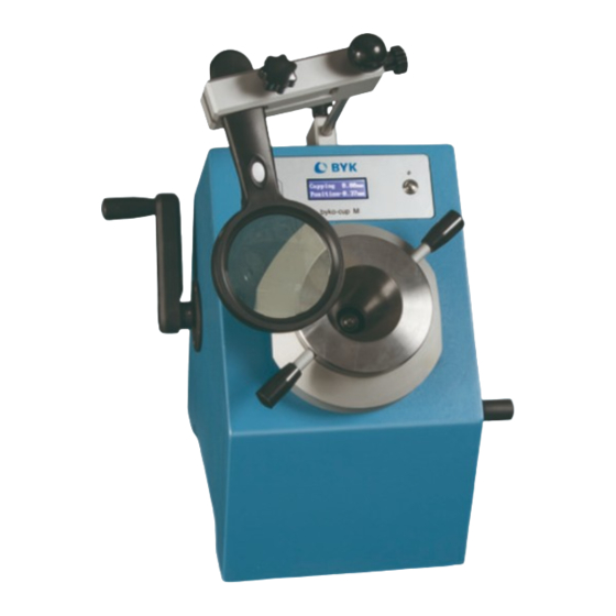
Information 1. Warning • The instrument must be securely positioned and fastened onto a level bench or table capable of supporting its weight. DO NOT: • use the instrument near water • clean the instrument with solvents (apart from the indenter and clamping system) •... - Page 6 Information 1. byko-cup M • Zero plate • Clamp ring • Operating handle • Button • LCD display • Base plate • Magnifying glass LCD display Operating handle Button Clamp ring Magnifying glass Operating handle Base plate Zero plate...
-
Page 7: System Description
System Description 2. System Description The Cupping Tester was originally designed to assess the resistance of coatings of paints varnishes (and related products) to cracking and/or detachment from the substrate under different conditions of controlled deformation. The instrument has since been redesigned and now includes: •... -
Page 8: Start-Up
Start-up 3. Start-up Unpacking: Carefully open the packaging, remove the smaller instruments before removing the instrument itself. Make sure all components in the component list are included. Installation: *Prior to installation, keep in mind that the instrument must not be exposed to; excessive heat or humidity, aggressive or corrosive substances, fl... - Page 9 Start-up 6. The magnifi er assembly is supplied separately. Slide the circular shaft through the clamp plate and tighten the clamping knob. Slide the shaft of the assembly into the receptacle on the instrument and tighten the clamp knob. Adjust to a position for optimum viewing of the sample.
-
Page 10: Operation
Operation 4. Operation 1. Power on the instrument with the switch located on the rear panel. Switch on the magnifi er, if required. 2. Rotate the operating handles counterclockwise (as viewed from the right- hand side of the instrument) to lower the hemispherical indenter just below the level of the bottom clamping ring. - Page 11 Operation Position The position display indicates the indenter’s position relative to the zero position. Loosen the clamping ring by turning counterclockwise and remove the zero plate. 5. Carefully pass the prepared test panel (coated side facing upwards) through the slot (at 90° to the operator) so that the center of the indenter is at least 35 mm from the edge of the test panel.
- Page 12 Operation use of the magnifying lens. The turn rate may be reduced slightly (in order to assist observation) at the fi rst sign of coating failure. Take the LCD cupping reading at the fi rst failure point. *For both methods turn the handle at a constant rate of 0.2 ±0.1 mm per second –...
- Page 13 Operation 13. Continue testing or switch off the instrument as required. Unplug the power supply if the instrument is not to be used for long periods. Operation Notes: The instrument will accommodate panels with a maximum width of 100mm. Reference to the test method recommends the use of burnished steel panels with a width and length of at least 70 mm and a thickness range of 0.3mm to 1.25mm...
-
Page 14: Maintenance
Maintenance 5. Maintenance The frequency of regular maintenance depends on the degree of use, together with the thickness of the test panels used – • Heavy use – every 3 months • Medium use – every 6 months • Low use – every 12 months 1. - Page 15 Maintenance Maintenance Schedule Between tests Clean the indenter and clamp system as necessary. Daily Check the zero-datum as required. Yearly Have the instrument serviced and calibrated by a trained and qualifi ed service engineer Cleaning Do not use solvent to clean the outer surfaces of the instrument.
-
Page 16: Components/Ordering Guide
Components/Ordering Guide 6. Components/Ordering Guide byko-cup M Cat No. 5415 Complies with: BS 3900, DIN 53166, DIN 53232, ISO 1520, JIS K 5600-5-2, JIS B 7729 Cat. No. Description 5415 byko-cup M 5416 Zero Plate 5417 Magnifi er 5418 Indenter Service and Spare Parts For all service and spare parts requirements please contact either:... -
Page 17: Technical Data
Technical Data 7. Technical Data byko-cup M 60 lbs Weight 27.2 kg 19.7 inches Height 500 mm 15.9 inches Width 405 mm 11.0 inches Depth 280 mm 0.8 inches Spherical Punch 20 mm +0.002 inches Full Range Accuracy +0.05 mm Full Range -0.02 –... - Page 20 199 025 440 E 1904...
Need help?
Do you have a question about the BYK byko-cup M and is the answer not in the manual?
Questions and answers