Table of Contents
Advertisement
Quick Links
Advertisement
Table of Contents

Related Manuals for VOLTCRAFT AO-610


Summary of Contents for VOLTCRAFT AO-610
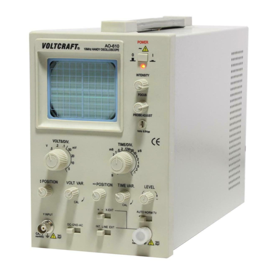
- Page 1 Voltcraft AO-610 10MHZ OSCILLOSCOPE USER’S MANUAL...
-
Page 2: Table Of Contents
CONTENTS 1. SAFETY PRECAUTIONS 2. SPECIFICATIONS 2.1 VERTICAL SYSTEM 2.2 TRIGGER SYSTEM 2.3 HORIZONTAL SYSTEM 2.4 X-Y MODE 2.5 CALIBRATION 2.6 CRT 2.7 POWER SOURCE 2.8 PHYSICAL FEATURES 2.9 WORKING ENVIRONMENT 2.10 PRESSURE-PROOF TEST 3. CONTROL AND INDICATORS 3.1 CONTROL PANEL POSITION 3.2 FUNCTIONS OF CONTROL SWITCHES 3.3 OPERATING INSTRUCTIONS... -
Page 3: Safety Precautions
1. SAFETY PRECAUTION The A oscilloscope is easy to operate and highly reliable. It is an ideal instrument for research, production, education, and development. It is a compact and portable oscilloscope with a frequency bandwidth of 10MHz and sensitivity of 5mV/DIV-5V/DIV. Supplied as standard, with a switchable X10: X1 probe which extends the sensitivity up to 50V/div. -
Page 4: Specifications
dangerous and should be strictly avoided. Take care not to allow water to get into this instrument. The use of this instrument in a wet state could result in electrical shock or fire. If water or other foreign matter has penetrated this instrument, first switch the power off, remove the power cord and call for repair. -
Page 5: X-Y Mode
2.4 X-Y MODE Sensitivity 0.2V/DIV〜0.5V/DIV Bandwidth(-3dB) DC: 0~1MHz AC: 10Hz~1MHz 2.5 CALIBRATION SIGNAL Waveform Symmetric Square Wave Range 05.V ±2% Frequency 1kHz ±2% 2.6 CRT Display Area 8 × 10DIV 1DIV=6mm Accelerating Voltage 1200V Display Color Green 2.7 POWER SOURCE Voltage Range 110V±10% , 220V±10%... -
Page 6: Control And Indicators
3. CONTROL AND INDICATORS 3.1 Control Panel Position 3.1.1 Front Panel Fig 3-1 3.1.2 Rear Panel Fig 3-2... -
Page 7: Functions Of Control Switches
3.2 FUNCTIONS OF CONTROL SWITCHES NO. SWITCHES FUNCTIONS POWER SWITCH Power on/off POWER LIGHT Lights when power on INTENSITY Controls brightness of display FOCUS After obtaining appropriate brightness with INTENSITY, adjust FOCUS for clearest line CALIBRATION Provide symmetric square wave for 0.5V range, frequency=1KHz. -
Page 8: Operating Instructions
3.3 OPERATING INSTRUCTIONS 3.3.1 VOLTAGE CHECKING A oscilloscope is set for 110V±10% , 220V ±10% voltage. Before connecting the unit to the mains supply, make sure that the correct voltage is being used. Incorrect mains voltage may cause damage to the instrument. 3.3.2 BASIC OPERATION (1) POSITION FOR CONTROL SWITCHES CONTROL SWITCHES... - Page 9 Fig 3-3 3.3.3 VERTICAL SYSTEM OPERATION (1) VOLTS/DIV switch should be turned to the correct position following the input signal range. Adjust position [16] to show the whole waveform within the available area. Adjust with VAR [17] if necessarily, trimming ratio is 2.5:1. (2) Input coupling options: “DC”is used for observing a signal with a direct current content such as logic or static signals, “DC”...
-
Page 10: Measurement
free run waveform requires a frequency higher than 20Hz; [11] “NORM”while waiting for sweep with no trace. When an input signal occurs the scope is triggered to sweep (3) and show the waveform . [10] “TV” used to determine TV signals. (4) SLOPE selection: Used to select whether the trigger signal crosses trigger level in a positive or a negative-going direction. - Page 11 shown in figure 4.1 (5) Observe the waveform compensation and adjust the LF compensation controls as shown in figure 4-2 Good Compensate Over Compensate Under Compensate Fig 4-1 LF COMP Fig 4-2 4.2 MEASUREMENT 4.2.1P-P Voltage Measurements Step : (1) Input signal to INPUT [19] terminal. (2) Setup VOLTS/DIV and observe waveform, set waveform display on the screen within 5 divisions, and turn VAR clockwise to the calibration position.
- Page 12 (5) Adjust vertical position to ensure the bottom of waveform lies on a horizontal axis on the screen. Fig 4-3A. (6) Adjust horizontal position to ensure the top of waveform lies center of vertical axis. Fig 4-3B. (7) Read the divisions between A-B on vertical direction. (8) Calculate the signal Vp-p using the formula below : Vp-p= DIV of vertical direction×...
-
Page 13: Time Measurements
Fig 4-4 Level Zero-volt Reference Level 4.3 TIME MEASUREMENTS 4.3.1 TIME SPACE MEASUREMENTS This is a procedure for making time (period) measurements between two points on a waveform: (1) Connect the signal to be measured to the input terminal [19]. (2) Adjust level to obtain steady waveform. - Page 14 4.3.2 CYCLE & FREQUENCY MEASUREMENTS Shown in Fig 4-6, frequency measurements are made by measuring the time period of one cycle of waveform (T), and calculating the frequency that equals the reciprocal of the time period. For example, T=16µS, then frequency is: F =1/T = ------------------ = 62.5 KHz 16 ×10 4.3.3 PULSE RISE TIME AND FALL TIME MEASUREMENTS...
-
Page 15: Y Mode Applications
4.4 TV Signals measurement Steps : (1) Connect TV signals to INPUT jack [19] (2) Set Trigger method to “TV” [10], Sweep switch turn to 2mS/Div. (3) Observe the screen, it should be negative synchronize pulse wave. (4) Adjust VOLTS/DIV and VAR to obtain proper range. 4.5 X–...
Need help?
Do you have a question about the AO-610 and is the answer not in the manual?
Questions and answers