Table of Contents
Advertisement
SERVICE MANUAL
AIR-CONDITIONER
INDOOR UNIT
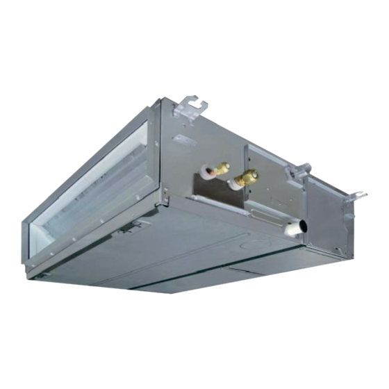
< Concealed Duct Standard Type >
MMD-AP0076BHPUL
MMD-AP0096BHPUL
MMD-AP0126BHPUL
MMD-AP0156BHPUL
MMD-AP0186BHPUL
MMD-AP0216BHPUL
MMD-AP0246BHPUL
MMD-AP0306BHPUL
MMD-AP0366BHPUL
MMD-AP0426BHPUL
MMD-AP0486BHPUL
MMD-AP0546BHPUL
R410A
FILE NO. SVM-20100-1
MULTI TYPE
Revised on December, 2020
Advertisement
Table of Contents
Troubleshooting

Related Manuals for Toshiba MMD-AP0076BHPUL


Summary of Contents for Toshiba MMD-AP0076BHPUL
- Page 1 FILE NO. SVM-20100-1 SERVICE MANUAL AIR-CONDITIONER MULTI TYPE INDOOR UNIT < Concealed Duct Standard Type > MMD-AP0076BHPUL MMD-AP0096BHPUL MMD-AP0126BHPUL MMD-AP0156BHPUL MMD-AP0186BHPUL MMD-AP0216BHPUL MMD-AP0246BHPUL MMD-AP0306BHPUL MMD-AP0366BHPUL MMD-AP0426BHPUL MMD-AP0486BHPUL MMD-AP0546BHPUL R410A Revised on December, 2020...
-
Page 2: Table Of Contents
CONTENTS PRECAUTIONS FOR SAFETY ................6 1. SPECIFICATIONS ....................11 2. FAN CHARACTER ISTICS..................15 3. CONSTRUCTION VIEWS (EXTERNAL VIEWS) ............ 17 4. WIRING DIAGRAMS ....................19 5. PARTS RATING ...................... 20 6. REFRIGERANT CYCLE DIAGRAM ............... 21 7. CONTROL OUTLINE ....................22 8. - Page 3 • The qualified service person is a person who installs, repairs, maintains, relocates and removes the air conditioners made by Toshiba Carrier Corporation. He or she has been trained to install, repair, maintain, relocate and remove the air conditioners made by Toshiba Carrier Corporation...
- Page 4 Definition of Protective Gear When the air conditioner is to be transported, installed, maintained, repaired or removed, wear protective gloves and ‘safety’ work clothing. In addition to such normal protective gear, wear the protective gear described below when undertaking the special work detailed in the table below.
- Page 5 Warning Indications on the Air Conditioner Unit [Confirmation of warning label on the main unit] Confirm that labels are indicated on the specified positions If removing the label during parts replace, stick it as the original. Warning indication Description WARNING WARNING ELECTRICAL SHOCK HAZARD ELECTRICAL SHOCK HAZARD...
-
Page 6: Precautions For Safety
PRECAUTIONS FOR SAFETY The manufacturer shall not assume any liability for the damage caused by not observing the description of this manual. DANGER Before carrying out the installation, maintenance, repair or removal work, be sure to set the circuit breaker for both the indoor and outdoor units to the OFF position. Otherwise, electric shocks may result. - Page 7 WARNIG Before starting to repair the air conditioner, read carefully through the Service Manual, and repair the air conditioner by following its instructions. Only qualified service person (*1) is allowed to repair the air conditioner. Repair of the air conditioner by unqualified person may give rise to a fire, electric shocks, injury, water leaks and / or other problems.
- Page 8 Do not modify the products.Do not also disassemble or modify the parts. It may cause a fire, electric shock or injury. Prohibition of modification. When any of the electrical parts are to be replaced, ensure that the replacement parts satisfy the specifications given in the Service Manual (or use the parts contained on the parts list in the Service Manual).
- Page 9 After repair work, surely assemble the disassembled parts, and connect and lead the removed wires as before. Perform the work so that the cabinet or panel does not catch the inner wires. If incorrect assembly or incorrect wire connection was done, a disaster such as a leak or fire is caused Assembly / at user’s side.
- Page 10 When the service panel of the outdoor unit is to be opened in order for the compressor or the area around this part to be repaired immediately after the air conditioner has been shut down, set the circuit breaker to the OFF position, and then wait at least 10 minutes before opening the service panel. If you fail to heed this warning, you will run the risk of burning yourself because the compressor pipes and other parts will be very hot to the touch.
-
Page 11: Specifications
1. SPECIFICATIONS Concealed Duct Standard type MMD-AP0076BHPUL MMD-AP0096BHPUL MMD-AP0126BHPUL Model name 7.50 9.50 12.0 Cooling Capacity (KBtu/h) 8.50 10.5 13.5 Heating Capacity (KBtu/h) 1Ph 60Hz 230V(208/230V) Power supply Running current 0.48 0.62 0.62 Electrical characteristics Power consumption (kW) 0.070 0.090 0.080... - Page 12 Concealed Duct Standard type Concealed Duct Standard type MMD-AP0156BHPUL MMD-AP0186BHPUL MMD-AP0216BHPUL Model name 15.4 18.0 21.0 (KBtu/h) Cooling Capacity 17.0 20.0 24.0 (KBtu/h) Heating Capacity 1Ph 60Hz 230V(208/230V) Power supply Running current 0.89 0.96 1.35 Electrical characteristics Power consumption (kW) 0.130 0.140 0.210...
- Page 13 Concealed Duct Standard type Model name MMD-AP0246BHPUL MMD-AP0306BHPUL MMD-AP0366BHPUL 24.0 30.0 36.0 (KBtu/h) Cooling Capacity (KBtu/h) 27.0 34.0 40.0 Heating Capacity 1Ph 60Hz 230V(208/230V) Power supply Running current 1.35 1.41 2.12 Electrical characteristics Power consumption (kW) 0.210 0.220 0.330 Starting current 2.15 2.21 2.92...
- Page 14 Concealed Duct Standard type MMD-AP0426BHPUL MMD-AP0486BHPUL MMD-AP0546BHPUL Model name 42.0 48.0 54.0 (KBtu/h) Cooling Capacity 47.5 54.0 60.0 (KBtu/h) Heating Capacity 1Ph 60Hz 230V(208/230V) Power supply Running current 2.12 2.18 2.18 Electrical characteristics Power consumption 0.330 0.340 0.340 (kW) Starting current 2.92 2.98 2.98...
-
Page 15: Fan Character Istics
2. FAN CHARACTER ISTICS AP0076 type AP0096, AP0126 type Standard air flow: 318 CFM Standard air flow: 395 CFM 0.80 0.70 0.60 0.6 in.WG- High tap 0.50 0.6 in.WG- High tap 0.4 in.WG- Mid 0.40 0.4 in.WG- Mid tap 0.30 0.4 in.WG- Low tap 0.4 in.WG-Low tap 0.4 in.WG- High tap... - Page 16 AP0486, AP0546 type AP0366, AP0426 type Standard air flow: 1130 CFM Standard air flow: 1177 CFM 0.8 in.WG- H 0.8 in.WG- High tap 0.6 in.WG- Mid tap 0.6 in.WG- Mid tap 0.6 in.WG- High tap 0.6 in.WG- High tap 0.6 in.WG- Low tap 0.6 in.WG- Low tap 0.4 in.WG- High tap 0.4 in.WG-...
-
Page 17: Construction Views (External Views)
3. CONSTRUCTION VIEWS (EXTERNAL VIEWS) Hanging bolt pitch B 0.9"(22) 29.5"(750) Main unit dimension A 2.0"(50) Hanging bolt pitch 650 2.0"(50) External dimensions of flange C 13.6"(345) 7.4" (187.5) 14.0"(355) 1.0"(25) Access panel Front View 16.3"(415) Electrical Drain pan / Drain control box 22.4"(570) pump check cover... - Page 18 AP0076, AP0096, AP0126 AP0156, AP0186 <Bottom air intake> <Bottom air intake> 37.8" 26.0" (959.4) (659.4) 1.5" 3.9" 3.9" 3.9" 3.9" 3.9" 3.9" 3.9" 3.9" 3.9" 1.5" 1.5" 3.9" 3.9" 3.9" 3.9" 3.9" 3.9" 1.5" (37.5) (100) (100) (100) (100) (100) (100) (100) (100)
-
Page 19: Wiring Diagrams
4. WIRING DIAGRAMS - 19 -... -
Page 20: Parts Rating
5. PARTS RATING 0076BHPUL 0096BHPUL 0126BHPUL 0156BHPUL 0186BHPUL Model MMD-AP ICF-340W150-2A ICF-340W150-1A Fan motor PMD-08D12TF-2 Drain pump motor Float switch FS-1A-31-3 PAM-MD12TF-301 Pulse motor valve 12.9" (328 mm) TA sensor Ø0.16"(4mm), 39.4" (1000mm) TC1 sensor Ø0.24"(6mm), 39.4" (1000mm) TC2 sensor Ø0.24"(6mm), 39.4"... -
Page 21: Refrigerant Cycle Diagram
6. REFRIGERANT CYCLE DIAGRAM Indoor unit Liquid side Gas side Strainer Capillary tube Heat exchanger Pulse Motor Valve (PMV) Distributor Sensor (TCJ) Sensor (TC2) Sensor (TC1) Sensor Fan motor (TA) Explanation of functional parts in indoor unit Functional part name Functional outline Pulse Motor Valve (Connector CN82 (6P): Blue) -
Page 22: Control Outline
7. CONTROL OUTLINE Indoor unit Control specifications Item Specification outline Remarks Upon power 1. Identification of outdoor unit supply reset When the power supply is reset, the outdoor unit is identified, and control is redirected according to the identification result. 2. - Page 23 Item Specification outline Remarks Fan speed 1. The fan operates in one of the four speed modes of “HIGH (HH)”, “MED HH > H+ > H > (H)”, “LOW (L)” and “AUTO” on the basis of a command issued via the L+ >...
- Page 24 Item Specification outline Remarks Cold air 1. In heating operation, the upper limit of the fan tap is set according to the TCJ: Indoor heat discharge lower of whichever is the higher between TC2 sensor and TCJ sensor exchanger prevention temperatures, on the one hand, and TC1 sensor temperature, on the sensor control...
- Page 25 Item Specification outline Remarks • Recovery operation Cooling oil While the outdoor unit is recovering cooling oil (refrigerant), the indoor normally takes (refrigerant) units perform the following control tasks: place roughly every recovery control [common for operational (cooling thermo ON / thermo OFF / FAN), as 2 hours.
- Page 26 Item Specification outline Remarks Filter sign 1. The indoor fan’s cumulative hours of operation are counted, and when “FILTER ” displayed display these exceed the prescribed value (2500H), a filter replacement signal (not applicable is sent to the remote controller to display a filter sign on it. to wireless type) 2.
- Page 27 Item Specification outline Remarks DC motor 1) When the fan operation has started, positioning of the stator and the Check code “P12” rotor are performed. (Moves slightly with tap sound) 2) The motor operates according to the command from the indoor controller.
-
Page 28: Applied Control And Functions (Including Circuit Configuration)
8. APPLIED CONTROL AND FUNCTIONS (INCLUDING CIRCUIT CONFIGURATION) 8-1. Indoor Controller Block Diagram (MCC-1720) 8-1-1. In case of connection of wired remote controller. Wired header remote controller (Up to 2 units) Schedule timer (weekly timer mode.) Display LCD Function setup Display LCD LCD driver Display LED... -
Page 29: In Case Of Connection Of Wireless Remote Controller
8-1-2. In case of connection of wireless remote controller. Display Operation Indoor unit #1 (Heder) (Follower) (Follower) Indoor control P.C. board (MCC-1720) EEPROM2 DC20V Remote controller EEPROM1 communication circuit DC5V TA sensor DC12V TC1 sensor Same as left Same as left TC2 sensor Drain Driver... -
Page 30: Controller
8-1-3. In case of connection of wired remote controller and Wireless remote controller. Schedule timer (weekly timer mode.) Wired header remote controller (Up to 2 units) Display LCD Function setup Display LCD LCD driver Display LED Key switch Function setup Key switch DC5V Remote controller... -
Page 31: Indoor Print Circuit Board Mcc-1631
8-2. Indoor Print Circuit Board MCC-1720 - 31 -... -
Page 32: Optional Connector Specifications Of Indoor P.c. Board
8-3. Optional connector specifications of indoor P.C. board Function Connector No. Pin No. Specification Remarks Fan output DC12 V Factory default setting: ON when indoor unit in operation and OFF when indoor unit at rest CN32 Output * Fan can be operated on its own by pressing FAN button on remote controller (DN = 31) Start / stop input Start / stop input for HA (J01: In place / Removed =... -
Page 33: Test Operation Of Indoor Unit
8-4. Test operation of indoor unit Check function for operation of indoor unit (Functions at indoor unit side) This function is provided to check the operation of the indoor unit singly without communication with the remote controller or the outdoor unit. This function can be used regardless of operation or stop of the system. However, if using this function for a long time, a trouble of the equipment may be caused. -
Page 34: Method To Set Indoor Unit Function Dn Code
8-5. Method to set indoor unit function DN code (When performing this task, be sure to use a wired remote controller.) <Procedure> To be performed only when system at rest Push the buttons simultaneously and hold for at least 4 seconds. The unit No. - Page 35 Function CODE No. (DN Code) table (includes all functions needed to perform applied control on site) Item Description At shipment Filter display delay timer 0000: None 0001: 150H According to type 0002: 2500H 0003: 5000H 0004: 10000H Dirty state of filter 0000: Standard 0000: Standard 0001: High degree of dirt (Half of standard time)
- Page 36 Type DN code “10” Value Type Model MMD-AP***BHPUL 0004 Concealed Duct Standard Indoor Unit Capacity DN code “11” Value Capacity 0000* Invalid 0001 007 type 0003 009 type 0005 012 type 0007 015 type 0009 018 type 0010 021 type 0011 024 type 0013...
-
Page 37: Applied Control Of Indoor Unit
8-6. Applied control of indoor unit Control system using remote controller interface (TCB-IFCB-4UL) Wiring and setting • In the case of group control, the control system functions as long as it is connected to one of the indoor units (control P.C. board) in the group. If it is desired to access the operation and error statuses of other units, relevant signals must be brought to it from those units individually. - Page 38 Ventilating fan control from remote controller [Function] • The start / stop operation can be operated from the wired remote controller when air to air heat exchanger or ventilating fan is installed in the system. • The fan can be operated even if the indoor unit is not operating. •...
- Page 39 Leaving-ON prevention control [Function] • This function controls the indoor units individually. It is connected with cable to the control P.C. board of the indoor unit. 2E 2E 2E 2E 2E • In a group control, it is connected with cable to the indoor unit (Control P.C. board), and the CODE No. is set to the connected indoor unit.
- Page 40 Manual address setting using the remote controller Procedure when setting indoor units’ addresses first under the condition that indoor wiring has been completed and outdoor wiring has not been started (manual setting using the remote controller) Wiring example of 2 refrigerant lines Refrigerant line 1 Refrigerant line 2 Outdoor...
- Page 41 <Line (system) address> 12 12 12 12 12 Push the TEMP. buttons repeatedly to set the CODE No. to Push the TIME buttons repeatedly to set a system address. (Match the address with the address on the interface P.C. board of the header outdoor unit in the same refrigerant line.) Push button.
- Page 42 Confirming the indoor unit addresses and the position of an indoor unit using the remote controller Confirming the numbers and positions of indoor units To see the indoor unit address of an indoor unit which you know the position of When the unit is individual (the indoor unit is paired with a wired remote controller one-to-one), or it is a group-controlled one.
- Page 43 To find an indoor unit’s position from its address When checking unit numbers controlled as a group TEMP. ON / OFF TIMER SET MODE TIME SAVE VENT Stop FILTER RESET TEST SWING/FIX UNIT LOUVER (Execute it while the units are stopped.) The indoor unit numbers in a group are indicated one after another.
- Page 44 To check all the indoor unit addresses using an arbitrary wired remote controller. (When communication wirings of 2 or more refrigerant lines are interconnected for central control) TEMP. ON / OFF TIMER SET MODE TIME SAVE VENT FILTER RESET TEST SWING/FIX UNIT LOUVER (Execute it while the units are stopped.)
- Page 45 Changing the indoor unit address using a remote controller To change an indoor unit address using a wired remote controller. The method to change the address of an individual indoor unit (the indoor unit is paired with a wired remote controller one-to-one), or an indoor unit in a group. (The method is available when the addresses have already been set automatically.) TEMP.
- Page 46 To change all the indoor unit addresses using an arbitrary wired remote controller. (The method is available when the addresses have already been set automatically.) (When communication wirings of 2 or more refrigerant lines are interconnected for central control) NOTE You can change the addresses of indoor units in each refrigerant line using an arbitrary wired remote controller.
- Page 47 TEMP. ON / OFF TIMER SET MODE TIME SAVE VENT FILTER RESET TEST SWING/FIX UNIT LOUVER Finish 5, 7 Press to finish setting Push the TIME buttons repeatedly to change the value of the indoor unit address in SET DATA. Change the value in SET DATA to that of a new address.
- Page 48 Error clearing function How to clear the error using the wired remote controller Clearing an error of the outdoor unit Clear the currently detected outdoor unit for each refrigerant line to which the indoor unit controlled by the remote controller is connected. (The indoor unit error is not cleared.) Use the service monitoring function of the remote controller.
- Page 49 Monitoring function of wired remote controller The following monitoring function is available if the remote controller of RBC-ATM32E is used. TEMP. ON / OFF TIMER SET MODE TIME SAVE VENT FILTER RESET TEST SWING/FIX UNIT LOUVER Content Enter the service monitoring mode using the remote controller to check the sensor temperature or operation status of the remote controller, indoor unit, and outdoor unit.
- Page 50 < Based on the SMMS-e > CODE No. Data name Display format Unit Remote control display example Room temperature (Use to control) ×1 °C [0027] = 27 °C Room temperature (Remote control) ×1 °C Indoor suction air temperature (TA) ×1 °F Indoor coil temperature (TCJ) ×1...
-
Page 51: Troubleshooting
9. TROUBLESHOOTING 9-1. Overview (1) Before engaging in troubleshooting (a) Applicable models All Super Module Multi (SMMS, SHRM, Mini-SMMS, SMMS-i) models. (Indoor units: MMO-APOOO, Outdoor units: MMY-MAPOOOO*, MCY-MAPOOOHT*) (b) Tools and measuring devices required • Screwdrivers (Philips, flat head), spanners, long-nose pliers, nipper, pin to push reset switch, etc. •... -
Page 52: Troubleshooting Method
9-2. Troubleshooting method The remote controllers (main remote controller and central control remote controller) and the interface P.C. board of an outdoor unit are provided with an LCD display (remote controller) or a 7-segment display (outdoor interface P.C. board) to display operational status. Using this self-diagnosis feature, the fault site / faulty part may be identified in the event of a fault by following the method described below. - Page 53 (Error detected by main remote controller) Check code Display of receiving unit Outdoor 7-segment display Indicator light block Main Typical fault site Description of error remote Operation Timer Ready controller Sub-code Flash Signals cannot be received from indoor unit; master remote No master remote controller, ⎯...
- Page 54 List of check codes (outdoor unit) IPDU: Intelligent Power Drive Unit (Inverter P.C. board) (Errors detected by SMMS outdoor interface - typical examples) :Lighting, : Flashing, : Goes off ALT.: Flashing is alternately when there are two flashing LED SIM: Simultaneous flashing when there are two flashing LED Check code Display of receiving unit Outdoor 7-segment display...
- Page 55 Check code Display of receiving unit TCC-LINK Outdoor 7-segment display Indicator light block Typical fault site Description of error central control or main remote Operation Timer Ready Sub-code Flash controller display Outdoor suction Outdoor suction temperature sensor (TS1) has – temperature sensor (TS1) been open / short-circuited.
- Page 56 Check code Display of receiving unit TCC-LINK Outdoor 7-segment display Indicator light block Typical fault site Description of error central control or main remote Operation Timer Ready Flash Sub-code controller display Address setting has not been performed for one or SIM Indoor group address not –...
- Page 57 (Errors detected by IPDU featuring in SMMS standard outdoor unit - typical examples) Check code Display of receiving unit TCC-LINK Outdoor 7-segment display Indicator light block Typical fault site Description of error central control or main remote OperationTimer Ready Flash Sub-code controller display...
-
Page 58: Troubleshooting Based On Information Displayed On Remote Controller
9-3. Troubleshooting based on information displayed on remote controller Using main remote controller (RBC-AMT32UL) (1) Checking and testing When a fault occurs to an air conditioner, a check code and indoor unit No. are displayed on the display window of the remote controller. Check codes are only displayed while the air conditioner is in operation. - Page 59 Using TCC-LINK central control remote controller (TCB-SC642TLE2) (1) Checking and testing When a fault occurs to an air conditioner, a Display of check code Display of Unit No. check code and indoor unit No. are displayed on the display window of the remote controller. UNIT No.
- Page 60 Using indoor unit indicators (receiving unit light block) (wireless type) To identify the check code, check the 7-segment display on the header unit. To check for check codes not displayed on the 7-segment display, consult the “List of Check Codes (Indoor Unit)” in “9-2. Troubleshooting method”. : Blinking (0.5 seconds) : Lighting : Goes off...
- Page 61 Light block Check code Cause of fault Heat exchanger temperature sensor (TCJ) error Operation Timer Ready Heat exchanger temperature sensor (TC2) error Indoor unit temperature sensor Heat exchanger temperature sensor (TC1) error errors Ambient temperature sensor (TA) error Alternate blinking Discharge temperature sensor (TF) error Discharge temperature sensor (TD1) error Operation Timer...
- Page 62 Light block Check code Cause of fault Operation Timer Ready Outdoor EEPROM error Synchronized blinking Other (indications not involving check code) Light block Check code Cause of fault Operation Timer Ready – Test run in progress Synchronized blinking Operation Timer Ready Setting incompatibility –...
-
Page 63: Check Codes Displayed On Remote Controller And Smms Outdoor Unit (7-Segment Display On I/F Board) And Locations To Be Checked
9-4. Check codes displayed on remote controller and SMMS outdoor unit (7-segment display on I/F board) and locations to be checked For other types of outdoor units, refer to their own service manuals. Check code Location Error detection Outdoor 7-segment display Main Description System status... - Page 64 Check code Location Error detection Outdoor 7-segment display Main Description System status Check items (locations) condition(s) remote Check detection controller Sub-code code Duplicated Indoor Duplicated All stop More than one indoor unit is Check indoor addresses. indoor address unit indoor address assigned same address.
- Page 65 Check code Location Error detection Outdoor 7-segment display Main Description System status Check items (locations) condition(s) remote Check detection Sub-code controller code Indoor Error in Stop of Periodic communication Check remote controller wiring. unit communication corresponding between indoor header and Check indoor power supply between indoor unit...
- Page 66 Check code Location Error detection Outdoor 7-segment display Main Description System status Check items (locations) condition(s) remote Check detection controller Sub-code code SMMS (Series 1) IPDU All stop Communication is disrupted • Check wiring and connectors 01: A3-IPDU1 error communication between IPDUs (P.C.
- Page 67 Check code Location Error detection Outdoor 7-segment display Main Description System status Check items (locations) condition(s) remote Check detection Sub-code controller code TL sensor All stop Sensor resistance is infinity Check connection of TL sensor error or zero (open / short connector.
- Page 68 Check code Location Error detection Outdoor 7-segment display Main Description System status Check items (locations) condition(s) remote Check detection controller Sub-code code Pd sensor All stop Output voltage of Pd Check connection of Pd sensor connector. error sensor is zero (sensor open-circuited).
- Page 69 Check code Location Error detection Outdoor 7-segment display Main Description System status Check items (locations) condition(s) remote Check detection controller Sub-code code Low oil level All stop Operating compressor <All outdoor units in protection detects continuous state of corresponding line to be low oil level for about 2 hours.
- Page 70 Check code Location Error detection Outdoor 7-segment display Main Description System status Check items (locations) condition(s) remote Check detection controller Sub-code code Compressor 2 All stop Compressor 2 case Check Compressor 2 case thermo case thermo circuit. thermo was activation activated.
- Page 71 Check code Location Error detection Outdoor 7-segment display Main Description System status Check items (locations) condition(s) remote Check detection Sub-code controller code SMMS Oil detection All stop The temperature Check the TK1 sensor installation. Check the TK1 sensor resistant (1 series) circuit error change of TK1 characteristics.
- Page 72 Check code Location Error detection Outdoor 7-segment display Main Description System status Check items (locations) condition(s) remote Check detection Sub-code controller code SMMS-i Oil level All stop No temperature Check for disconnection of TK4 sensor. detection change is detected (4 series) Check resistance characteristics of circuit error by TK4 despite...
- Page 73 Check code Location Error detection Outdoor 7-segment display Main Description System status Check items (locations) condition(s) remote Check detection Sub-code controller code Outdoor All stop Jumper wire provided on P.C. Check model setting of P.C. capacity not set board for servicing I/F P.C. board for servicing outdoor board has not been removed I/F P.C.
- Page 74 Check code Location Error detection Outdoor 7-segment display Main Description System status Check items (locations) condition(s) remote Check detection Sub-code controller code Detected indoor Indoor External Stop of Signal is present at When external device is address unit interlock of corresponding external error input connected to CN80...
- Page 75 Check code Location Error detection Outdoor 7-segment display Main Description System status Check items (locations) condition(s) remote Check detection controller Sub-code code Open phase detected, All stop Phase sequence Check the phase sequence of Phase sequence error error was detected outdoor power wiring.
- Page 76 Check code Location Error detection Outdoor 7-segment display Main Description System status Check items (locations) condition(s) remote Check detection controller Sub-code code Outdoor liquid All stop <During cooling operation> Check full-close operation backflow When system is in cooling of outdoor PMV (1, 2, 4). detection error operation, high pressure is Check for defect in Pd or...
- Page 77 Check code Location Error detection Outdoor 7-segment display Main Description System status Check items (locations) condition(s) remote Check detection controller Sub-code code Detected 4-way valve All stop Abnormal refrigerating cycle Check for defect in main outdoor unit reversing error data is collected during body of 4-way valve.
- Page 78 Check code Location Error detection Outdoor 7-segment display Main Description System status Check items (locations) condition(s) remote Check detection Sub-code controller code SMMS (Series 1) Outdoor fan All stop (Sub code: 08) Check the fan motor. Check the connector 08: Out of step IPDU error FAN IPDU position detection connection for fan motor.
- Page 79 Check code Location Error detection Outdoor 7-segment display Main Description System status Check items (locations) condition(s) remote Check detection Sub-code controller code ∗ SMMS-i IPDU Outdoor fan All stop Check fan motor. (Sub code: 0 (Series 4) IPDU error Check for defect in fan Fan IPDU over current ∗...
- Page 80 Errors detected by TCC-LINK central control device Check code Location Error detection Outdoor 7-segment display Main Description System status Check items (locations) condition(s) remote Check detection Sub-code controller code TCC-LINK TCC-LINK Continued Central control device is Check for defect in central operation unable to transmit signal.
- Page 81 Part name Checking procedure Concealed Duct type Measure the resistance value of each winding by using the tester. Fan motor ICF-340W150-2A ICF-340W150-1A, 2A MMD-AP0076BHPUL Position Resistance value AP0096BHPUL AP0126BHPUL 14.8 ± 1.5 Ω Black–Red 14.8 ± 1.5 Ω Black–White ICF-340W150-1A Fan motor inside wiring diagram 14.8 ±...
-
Page 82: Sensor Characteristics
9-5. Sensor characteristics Indoor unit Temperature sensor characteristics Indoor TA sensor Temperature [˚C] Resistance [kΩ] 33.9 Resistance 26.1 [kΩ] 20.3 15.9 12.6 10.0 Temperature [˚C] Temperature [˚C] Resistance [kΩ] –20 99.9 –15 74.1 Indoor TC1 sensor –10 55.6 –5 42.2 32.8 25.4 19.8... -
Page 83: Replacement Of P.c.board For Indoor Unit Serviceing
(MCC-1720) 10. Replacement of P.C. Board for Indoor Unit Servicing <Models> MMD-AP****BHPUL Series <Note> when replacing the P.C.board for indoor unit servicing> The nonvolatile memory (hereafter called EEPROM, IC503) on the in door unit P.C.board before replacement includes the model specific type information and capacity codes as the factory-set value and the important setting data which have been automatically or manually set when the indoor unit is installed, such as system/indoor/group addresses, high ceiling select setting, etc. - Page 84 TEST Step 3 After writing down all setting data, press button to return to the normal stop status. (It takes approx. 1 min until the remote control operation is available again.) CODE No.required at least 1. The CODE No. for the Indoor unit type and Indoor unit capacity Contents are required to set the rotation number setting of the fan.
- Page 85 UNIT LOUVER Step 2 Every time when the button is pressed, the indoor unit Nos. in the group control operation are displayed in order. (The settings stored in the EEPROM of the P.C. board for indoor unit servicing are the factory-set values.) Specify the indoor unit No.with its P.C.
- Page 86 Table 1.Setting data(CODE No. table(example)) Item Setting data Factory-set value Filter display delay timer 0002 : 2500H Dirty state of filter 0000 : Standard Central control address 00Un/0099 : Unfixed Specific indoor unit priority 0000 : No priority Heating suction temperature shift Automatic mode 0001 : No automatic Cooling only...
-
Page 87: Detachments
NOTE In a section, Detachments, the models are expressed as follows for convenience. AP007 : MMD-AP0076BHPUL to MMD-AP0126BHPUL AP015 : MMD-AP0156BHPUL to MMD-AP0186BHPUL AP021 : MMD-AP0216BHPUL to MMD-AP0546BHPUL Part name... - Page 88 Part name Procedure Remarks Suction panel 1. Detachment 1) Remove the fixing screws A which fix the suction panel. Loosen the fixing screws B. 2) Slide the suction panel to the arrow side and then remove the panel. 2. Attachment 1) Hook the suction panel to the fixing screws B and tighten screws.
- Page 89 Part name Procedure Remarks Electric parts 1. Detachment 1) Perform works of 1 of (In case of under air intake) Perform works of 1 of (In case of back air intake) Perform works of 1 of 2) Remove the indoor/outdoor connecting wire and remote controller wire from each terminal block.
- Page 90 Part name Procedure Remarks Fan motor, 1. Detachment Fan, 1) Perform works until opening of the electric parts box cover in works of 1 of Fan case 2) Remove connectors for fan motor wiring from control P.C. board. CN333 : Motor power supply (5P: White) CN334 : Motor control (5P: White) 3) Open the fan case (under) and remove it while pressing claws of the fan case...
- Page 91 Part name Procedure Remarks Drain pan 1. Detachment 1) Remove the drain cap and then extract the Bottom base drain water accumulated in the drain pan. NOTE Do not hold the When removing the drain cap, be sure to drain socket. receive drain water using a bucket, etc.
- Page 92 Part name Procedure Remarks Heat 1. Detachment : Screw position exchanger 1) Recover the refrigerant gas and then remove the refrigerant pipe of the indoor AP007 Type unit. Heat exchanger End plate 2) Perform works of 1 of fixed plate 3) Pull out TC sensor and TCJ sensor wirings from the holder.
-
Page 93: Exploded Views And Parts List
12. EXPLODED VIEWS AND PARTS LIST 12-1. Concealed duct standard type MMD-AP0076BHPUL, MMD-AP0096BHPUL, MMD-AP0126BHPUL - 93 -... - Page 94 Model name MMD-AP Location Part No. Description 0076BHPUL 0096BHPUL 0126BHPUL 43T21519 MOTOR,FAN 43T20340 FAN, MULTI BLADE 43T70315 HOSE, DRAIN 43T44709 REFRIGERATION CYCLE ASSY 43T22335 CASE, FAN, LOWER 43T22337 CASE, FAN, UPPER 43T72317 PAN ASSY, DRAIN 43T82319 SOCKET 43T79321 CAP, DRAIN 43T70319 ASM-HOSE-DRAIN 43T39356...
- Page 95 MMD-AP0156BHPUL, MMD-AP0186BHPUL - 95 -...
- Page 96 Model name MMD-AP Location Part No. Description 0156BHPUL 0186BHPUL 43T21509 MOTOR-FAN 43T20340 FAN, MULTI BLADE 43T70315 HOSE, DRAIN 43T44711 REFRIGERATION CYCLE ASSY 43T22335 CASE, FAN, LOWER 43T22337 CASE, FAN, UPPER 43T72317 PAN ASSY, DRAIN 43T82319 SOCKET 43T79321 CAP, DRAIN 43T70319 ASM-HOSE-DRAIN 43T39356 FLANGE...
- Page 97 MMD-AP0216BHPUL, MMD-AP0246BHPUL, MMD-AP0306BHPUL, MMD-AP0366BHPUL - 97 -...
- Page 98 Model name MMD-AP Location Part No. Description 0216BHPUL 0246BHPUL 0306BHPUL 0366BHPUL 43T21511 MOTOR-FAN 43T20339 FAN, MULTI BLADE 43T70315 HOSE, DRAIN 43T44712 REFRIGERATION CYCLE ASSY 43T22336 CASE, FAN, LOWER 43T22338 CASE, FAN, UPPER 43T72319 PAN ASSY, DRAIN 43T82318 SOCKET 43T79321 CAP, DRAIN 43T70319 ASM-HOSE-DRAIN 43T39358...
- Page 99 MMD-AP0426BHPUL, MMD-AP0486BHPUL, MMD-AP0546BHPUL - 99 -...
- Page 100 Model name MMD-AP Location Part No. Description 0426BHPUL 0486BHPUL 0546BHPUL 43T21511 MOTOR-FAN 43T20339 FAN, MULTI BLADE 43T70315 HOSE, DRAIN 43T44712 REFRIGERATION CYCLE ASSY 43T22336 CASE, FAN, LOWER 43T22338 CASE, FAN, UPPER 43T72319 PAN ASSY, DRAIN 43T82318 SOCKET 43T79321 CAP, DRAIN 43T70319 ASM-HOSE-DRAIN 43T39358...
- Page 101 12-2. Electric Parts CN104 IC501 IC503 SW501 CN33 RY01 CH-49-Z-T Lot No. R DB01 CN01 Model name MMD-AP Location Part No. Description 0076 0096 0126 0156 0186 0216 0246 0306 0366 0426 0486 0546 BHPUL BHPUL BHPUL BHPUL BHPUL BHPUL BHPUL BHPUL BHPUL...
- Page 102 144/9 MOO 5, BANGKADI INDUSTRIAL PARK, TIVANON ROAD, TAMBOL BANGKADI, AMPHUR MUANG, PATHUMTHANI 12000, THAILAND.
Need help?
Do you have a question about the MMD-AP0076BHPUL and is the answer not in the manual?
Questions and answers