
Subscribe to Our Youtube Channel
Related Manuals for Adastra LA-Series


Summary of Contents for Adastra LA-Series
- Page 1 LA-SERIES LOOP AMPLIFIERS Item ref: 952.864UK, 952.867UK User Manual Version 1.1 Caution: Please read this manual carefully before operating Damage caused by misuse is not covered by the warranty...
- Page 2 SAFETY SYMBOL AND MESSAGE CONVENTIONS CAUTION AVIS RISK OF ELECTRIC SHOCK RISQUE DE CHOC ELECTRIQUE NE PAS DO NOT OPEN OUVRIR This symbol indicates that dangerous voltage constituting a risk of electric shock is present within this unit This symbol indicates that there are important operating and maintenance instructions in the literature accompanying this unit.
-
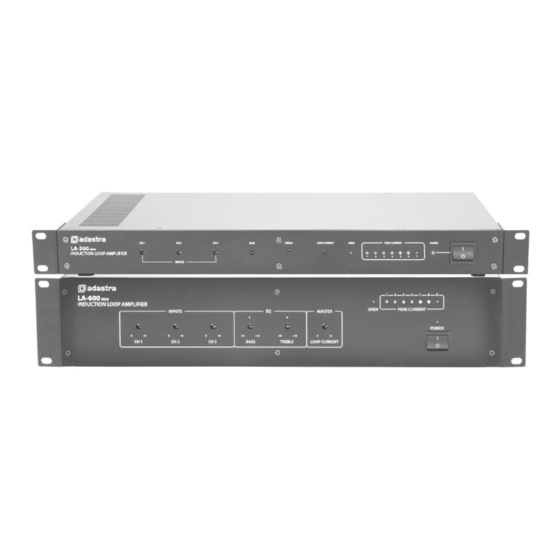
Page 3: Front Panel
Introduction Thank you for choosing an Adastra LA series induction loop amplifier for your assisted hearing installation. This unit is designed to offer high quality hearing assistance for hearing aid users. Please read this manual fully and follow the instructions to achieve the best results with your new purchase and to avoid damage through misuse. -
Page 4: Installation
Installation The LA series loop amplifiers can be operated free-standing or fitted into a standard 19” rack cabinet using the supplied rack ears. Ensure that the unit is positioned on a stable surface with adequate cooling ventilation. There are 3 input channels which can accept inputs via balanced XLR or 6.3mm jack connection (14) or unbalanced RCA connection(15). - Page 5 It is recommended to use good quality insulated pure copper cable for the induction loop. The cable gauge used will need to be determined by the total length of the cable run. The LA-series loop amplifiers are designed to operate with a load of between 0.2Ω and 2Ω. The following equation can be used to calculate the total cable resistance, which will show if the gauge is correct.
- Page 6 Cancellation Loops If there are areas adjacent to the loop where the magnetic field would cause problems, it is possible to avoid this by use of a “cancellation loop”, which is a narrow loop parallel to the main loop at the problem area. This loop is the opposite polarity to the main loop and causes the magnetic field to narrow along the adjacent edge of the main loop to control the spill of the loop field.
-
Page 7: Operation
Operation The front panel controls on the loop amplifier are recessed and can be adjusted using a flat blade screwdriver. This is to avoid tampering or mal-adjustment after the correct settings have been applied. Where new or unsupervised operators are making adjustments to equipment in the venue, they may not be aware if they have adjusted the induction loop settings unless they themselves are a hearing aid user. -
Page 8: Specifications
Specifications Model LA-300 mkII (952.864UK) LA-600 mkII (952.867UK) Power supply 110/240Vac, 50/60Hz (IEC) Fuse T1A 250V T2A 250V Area coverage 300m² max. 600m² max. Frequency response 50Hz - 5kHz (±3dB) Input sensitivity : line -6dBu/6k Ohms Input sensitivity : mic -56dBu/2k Ohms Signal to noise ratio 75dB (line), 60dB (mic)
Need help?
Do you have a question about the LA-Series and is the answer not in the manual?
Questions and answers