
Related Manuals for Efitment T016


Summary of Contents for Efitment T016
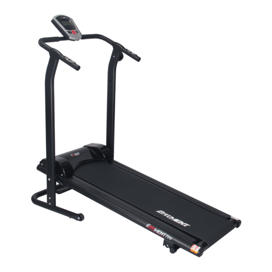
- Page 1 T016 ADJUSTABLE INCLINE MAGNETIC MANUAL TREADMILL USER MANUAL IMPORTANT! Read all instructions carefully before using this product. Retain this manual for future reference. For customer service, contact service@zoovaa.com.
- Page 3 PRECAUTIONS WARNING:TO REDUCE THE RISK OF SERIOUS INJURY, READ THE FOLLOWING IMPORTANT PRECAUTIONS BEFORE USING THE TREADMILL. 1. Read all instructions in this instruction book before using the treadmill. Use the treadmill only in the way described in this instruction book. 2.
-
Page 4: Exploded View
EXPLODED VIEW... -
Page 5: Part List
PART LIST DESCRIPTION Main frame Bottom frame Left side hand post Right side hand post Handle bar Base of the magnet Front roller Front axle Rear roller Rear axle Bolt M6*75L Washer OD13*ID6.2 Bolt M6*75L Bolt M5*20L Bolt M3*10L Sensor wire connector Bolt M8*45L Bolt M5*20L Bolt M6... - Page 6 PART LIST DESCRIPTION End cap Front end cap Plastic cover Plastic wheel Base frame cushion Computer Plug Plastic end cap Magnet Running board Running belt Tension knob Incline Adjuster Bolt M8*15L Bolt M6*10L Bolt M8*45L Bolt M4*12L Bolt M10*60L Washer OD16*ID8.3 Arc washer OD16*ID8.3 Washer OD22*ID10.3...
- Page 7 ASSEMBLY NOTICE Read this manual before assembly. Check that you have all the parts for assembly. Check the hardware. Ensure that you have the right tool. Prepare an area to assemble. Follow the instructions accordingly. ...
- Page 8 ASSEMBLY DESCRIPTION Q’TY NO. DESCRIPTION Q’TY Main Frame Handle Bar Bottom Frame Plastic Cover Left Side Hand Post Computer Right Side Hand Post Cover of Handle...
-
Page 9: Assembly Parts List
ASSEMBLY PARTS LIST... - Page 10 ASSEMBLY NOTE: The assembly parts list is included for your reference. Some parts are preassembled on the machine. In these instances, simply remove and reinstall the parts as required. STEP 1 Attach Right and Left Side Hand Posts (3 & 4) to the Bottom Frame (2), then fasten them with Bolts, Washers and Arc Washers (A, F &...
- Page 11 STEP 2 Before you assemble the tension cable, make sure HIGH that it is at level 8. To assemble the magnetic tension adjustment mechanism: 1. Insert tension wire into the gap in Baffle Plate (R), then lower Steel Wire Cap (T) into the hole in R. Then insert tension wire into the gap in Tension Permanent Seat (S), keeping Tension Net (U) between Baffle Plate (R) and Tension Permanent Seat (S).
- Page 12 2.Pull Tension Sleeve (X) downward to bring Baffle Plate (R) close to Tension Permanent Seat (S), then insert V into Tension Permanent Seat (S). 3. Turn Tension Nut (U) clockwise in order to tighten Tension Nut (U) and Tension Bolt (V) well.
- Page 13 STEP 3 Cover the flywheels with Plastic Cover (38), then secure it with Screws (B) and Washer (K). STEP 4 Ensure the holes are aligned. Stabilize the Right and Left Side Hand Posts (3 & 4) and raise the Main Frame (1). Attach Right and Left Side Hand Posts (3 &...
- Page 14 STEP 5 Connect the Sensor Wire Connectors (24 & 22). STEP 6 Place the Handrail (5) onto the Right and Left Side Hand Posts (3&4) and secure them with Bolts (C) and Arc Washers (G). Connect the Sensor Wire Connectors (17 & 22). Put the Cover of Handle (34) on the handle bar.
- Page 15 STEP 7 Unscrew Bolt (D) and Washer (I) from plastic base of the Computer (41). Attach the Computer (41) to the Handrail (5), insert the Sensor Wire Connector (17) and the Hand Pulse Connector (26) into the Computer (41), and then secure with Bolt (D) and Washer (I).
-
Page 16: Adjusting The Incline
NOTE: Always use proper lifting technique to prevent injury. ADJUSTING THE INCLINE There are 3 incline angles (A: 7°, B: 8°, C: 9° ). To adjust the incline, lift the rear end of the main frame up, and use your other hand to adjust the incline adjuster to the desired position. -
Page 17: Adjusting The Belt
FOLDING Loosen Knob (J) completely before folding. Lift Main Frame to the upright position. Put Knob (J) back in and tighten. ADJUSTING THE BELT If the belt is not centered correctly, the machine will be noisy. If the belt is too tight, too loose or not centered, use the 5mm wrench to adjust 1. -
Page 18: Adjusting The Tension
ADJUSTING THE TENSION The user can set the desired tension according to the picture below: To decrease the tension, turn Bolt (13) clockwise. To increase the tension, turn Bolt (13) counterclockwise. After adjusting the Bolt (13), check if the tension wire is too loose. If necessary, adjust the Bolts (U or W) on tension wire. -
Page 19: Maintenance
MAINTENANCE Treadmill Lubrication To reduce the friction of the walking belt and minimize wear, apply lubricant directly onto the Treadboard and underside of the Belt. Lift one side of the Belt and feel the top surface of the Treadboard. If the surface is wet to the touch, no lubrication is required. -
Page 20: How To Move The Treadmill
HOW TO MOVE THE TREADMILL Before attempting to move the treadmill, please make sure that it has been properly folded. The Knob (J) must be tightened. Start by placing two hands at position "25" to support the treadmill. Next, please place one foot at position "39"... - Page 21 OPERATING INSTRUCTIONS TIME………………………………………………….……........….00:00~99:59 MIN SPEED………………………………………………… ......0.0~99.99 MI /H D I S TA N C E … … … … … … … … … … … … … … … … … … . … ....0 . 0 ~ 9 9 9 . 9 M I CA L O R I E …...
Need help?
Do you have a question about the T016 and is the answer not in the manual?
Questions and answers