
Subscribe to Our Youtube Channel
Related Manuals for ICT ICT180S-12IRC


Summary of Contents for ICT ICT180S-12IRC
- Page 1 The Power of Reliability ICT180S-12IRC INTELLIGENT MODEL WITH REMOTE POWER CONTROL (SERIES 2) INSTRUCTION MANUAL Distributed by www.airadio.com...
-
Page 3: Table Of Contents
TABLE OF CONTENTS Warnings Page 2 Product Description Page 3 Installation Page 4 LCD/Select Button Operation Page 7 Web-Based Configuration Utility Page 9 Status & Control Page 10 Device Setup Page 11 Output Setup Page 13 Network Setup Page 16 E-mail Setup Page 18 Alarm Setup... -
Page 4: Warnings
Use wire and connectors rated for the maximum load current and size of fuse or circuit breaker Carefully observe wiring polarity when making input and output connections Securely tighten all connections and insert fuses fully No internal user serviceable parts. Refer all product service to an authorized ICT Ltd. service facility CAUTION Risk of personal injury or damage to equipment! Always observe the following: Fuses may be HOT to touch. -
Page 5: Product Description
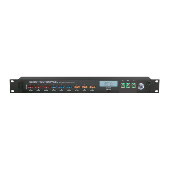
PRODUCT DESCRIPTION The ICT180S-12IRC Intelligent Distribution Panel with Remote Power Control is designed for either 12 or 24VDC applications. It provides 12 output positions that are individually protected by blade type fuses. Nine of the outputs use ATO/ATC blade fuses that are rated up to 25A each. Three of the outputs use JCASE fuses and are rated up to 40A each. -
Page 6: Installation
BACK PANEL Figure 2. 1. NEGATIVE INPUT STUD: For DC power source connection up to 180A peak and 150A continuous. 2. OUTPUT TERMINAL BLOCK 10 – 12: For DC load connections up to 40A each pair. 3. ALARM FORM “C” CONTACTS: For external alarm circuit to monitor alarms generated by the panel. 4. - Page 7 4. Install fuse on the front of the panel for each output terminal block. The fuse number on the front of the panel matches the output terminal block number on the back of the panel. Consult your local electrical codes for wire ampacity and fuse sizing. Typically, fuses and wiring are derated to 80% of their rating (e.g.
- Page 8 NC/C PINS NO/C PINS CONDITION Fuse Alarm Activate Alarm Form C Contact is checked • One or more blown or missing fuse • System Under - Voltage Alarm Activate Alarm Form C Contact is checked • System Voltage is below the set value •...
-
Page 9: Lcd/Select Button Operation
LCD/SELECT BUTTON OPERATION At power up, the LCD of the panel will display the main screen. To switch between the various LCD screens, press the Output Select button on the front of the panel (see Figure 3 for screen order). Figure 3: LCD Screens Holding the Output Select button for 2 seconds at any screens will return you to the main screen. - Page 10 MAIN SCREEN Line 1: Displays the name of the panel, which is customizable through the web-based configuration utility. Line 2: blank Line 3: Displays the system voltage. Voltage display will blink if the system voltage exceeds the Under-Voltage or Over-Voltage Thresholds set on the Alarm Setup page. Line 4: Displays the system current.
-
Page 11: Web-Based Configuration Utility
WEB-BASED CONFIGURATION UTILITY Follow these steps to access the panel from a browser. The recommended web browsers to use with this panel are Microsoft Internet Explorer, Mozilla Firefox or Google Chrome. 1. Start your web browser. 2. Enter the IP address of the panel in the location/address field of the browser. Figure 4. -
Page 12: Status & Control
4. Once connected, the panel Status & Control page will appear in your browser window. Figure 6. STATUS & CONTROL This page provides information on system voltage, system current, alarm status, output status, and current level by output contact (1 through 12). It also allows you to manually enable or disable DC power to the each of the output terminals. -
Page 13: Device Setup
DEVICE SETUP This page allows you to configure the device settings of the panel. To save any changes to the device settings, click on Save Settings at the bottom of this page. DEVICE INFO Site Name: Allows you to assign a custom name to the panel. Model: Displays the model number of the panel. - Page 14 Reverse Sequence Order: If this box is checked, the outputs will be enabled in reverse sequence (Output #12 first, Output #1 last) when the Enable All Outputs button is pressed on the Status & Control page. NETWORK WATCHDOG Watchdog Enabled: Checking this box will enable the Network Watchdog feature. The Network Watchdog will periodically Ping up to two remote IP address to check the network connection status.
-
Page 15: Output Setup
OUTPUT SETUP This page allows you to configure the output settings of the panel. In the Select an Output to edit box, click on the output number of the output you wish to configure. To save any changes to the output settings, click on Save Settings at the bottom of this page. - Page 16 OUTPUT LOAD-SHEDDING Load-Shedding: Allows you to turn on load-shedding for the selected output. Load-shedding automatically disables DC power to the output when the system voltage drops below the load-shedding threshold voltage. The system voltage must remain below the load-shedding threshold voltage for at least 30 seconds before the output will be disabled.
- Page 17 OUTPUT UNDER-CURRENT ALARM Under-Current Threshold: If the current on the selected output drops below the value in this field, the output under-current alarm will trigger. The output current must remain below the under-current threshold for at least 5 seconds before the alarm will be triggered.
-
Page 18: Network Setup
NETWORK SETUP WARNING: Changing the network settings will reboot the panel.. This page allows you to configure the network settings of the panel. To save any changes to the network settings, click on Save Settings at the bottom of this page and panel will reboot. NETWORK MAC Address: Displays the MAC address assigned to the panel. - Page 19 SNMP Configure these settings if you would like to use SNMP monitoring. SNMP (Simple Network Management Protocol) is the industry standard protocol for network management software. When SNMP is enabled on the panel, it allows standard SNMP management software to connect to the SNMP agent running on the panel and read real-time system information such as voltage and current.
-
Page 20: E-Mail Setup
E-MAIL SETUP Configure these settings if you would like to receive e-mail alarm notifications from the panel. The information for the following settings is available from your Network Administrator or Internet Service Provider (ISP). E-MAIL SMTP Server: The name or IP address of your SMTP server used for sending outgoing e-mail. SMTP Server requires SSL: Check this box if your SMTP Server requires an encrypted SSL connection. -
Page 21: Alarm Setup
ALARM SETUP This page allows you to select which alarms you wish to monitor, and also allows you to enter custom thresholds for each status condition. To save any changes to the alarm settings, click on Save Settings at the bottom of this page. FUSE ALARM Activate Alarm Form C Contact: If this box is checked, the alarm form “C”... - Page 22 SYSTEM OVER-CURRENT ALARM Over-Current Threshold: If the total system current rises above the value in this field, the system over-current alarm will trigger. The system current must remain above the over-current threshold for at least 5 seconds before the alarm will be triggered. Activate Alarm Form C Contact: If this box is checked, the alarm form “C”...
-
Page 23: User Setup
USER SETUP This page allows you to configure passwords for accessing the panel. To save any password changes, click on Save Settings at the bottom of this page. The Administrator account has no password assigned to it by default. For improved security, it is recommended that you assign a password to the account. -
Page 24: Maintenance
MAINTENANCE This page allows you to reset the panel, restore the panel to factory default settings, and send test e-mail to verify that functionality. RESET DISTRIBUTION PANEL Pressing the Reset button will restart the Distribution Panel. Output states will be set according to the “Output State after Panel Reset”... -
Page 25: Mobile Web App
MOBILE WEB APP A mobile version of the Status & Control page is available which is optimized for smartphone web browsers. To access the Mobile Web App, type the address of the panel in the location/address field of the browser on your smartphone, followed by /m (e.g. -
Page 26: Password Reset
PASSWORD RESET Resetting the password resets the Administrator password, network and web server settings to the original factory default values. The Standard User password is not affected. To reset, do the following: 1. Press and hold the Output Select button on the front of the panel (approximately 20 seconds) until Resetting is shown on the LCD. - Page 27 Figure 8. 3. To configure HTTPS forwarding, repeat steps 2a – 2e with the HTTPS port number that the panel is using. If you are using the default panel port settings, the HTTPS port number is 443. 4. To set up your router to allow remote panel firmware upgrades, repeat steps 2a – 2e with the UDP port number that the panel is using.
- Page 28 Figure 9. 6. To access the panel over the Internet, type the WAN IP Address of the router in the location/address field of your browser, followed by a colon and the HTTP port number that the panel is using (e.g. http://209.123.10.33:8000 for IP Address 209.123.10.33, Port 8000). Figure 10.
-
Page 29: Text Message Alarm Notifications
TEXT MESSAGE ALARM NOTIFICATIONS The panel can send text message alarm notifications to a cell phone by sending the alarm e-mail to an address at the mobile phone provider. On the E-mail Setup page, enter the address for your phone in the Recipient E-mail Addresses field. -
Page 30: Troubleshooting
TROUBLESHOOTING I am unable to access the web-based configuration utility: Check that you are using the correct IP address to access the panel by pressing the Output Select button on the front of the panel to view the Network Status screen on the LCD. The IP address for the panel may have changed if DHCP is enabled. -
Page 31: Product Specifications
PRODUCT SPECIFICATIONS Operating Voltage: 10 to 30VDC Panel Capacity: 150A (Continuous) 180A (Peak) Fuse Capacity: 25A Maximum ATO/ATC Blade x 9 40A Maximum JCASE x 3 Note 1: Ensure that the load total connected to the fused outputs does not exceed the panel capacity rating. Note 2: Most fuses should be continuously operated at no more than 80% of their nominal current rating. -
Page 32: Limited Warranty
In no event will ICT be liable for any damages resulting from the use of or the inability to use the ICT product, even if an ICT employee or an authorized ICT dealer has been advised of the possibility of such damages, or for any claim by any other party.
Need help?
Do you have a question about the ICT180S-12IRC and is the answer not in the manual?
Questions and answers