
Subscribe to Our Youtube Channel
Related Manuals for ICT ICT200DF-12IRC


Summary of Contents for ICT ICT200DF-12IRC
- Page 1 Innovative Circuit Technology Ltd. Dual Bus Distribution Panel Series INSTRUCTION MANUAL 855-314-000 Models: ICT200DF-12IRC ICT200DB-12IRC...
- Page 2 Securely tighten all connections Do not attempt to service any internal parts. Refer all product service to an authorized ICT Ltd. service facility CAUTION Risk of personal injury or damage to equipment! Always observe the following: Install unit in a restricted access location (such as an equipment rack) to limit ...
-
Page 3: Table Of Contents
Contents PRODUCT DESCRIPTION ............... 4 INSTALLATION ..................5 OPERATION ..................8 LCD Display ..................... 9 Status Indicators and Alarms ..............11 TCP/IP WEB BASED UTILITY ..............12 Status and Control ................14 Device Setup ..................15 Bus Setup ....................17 Output Setup .................. -
Page 4: Product Description
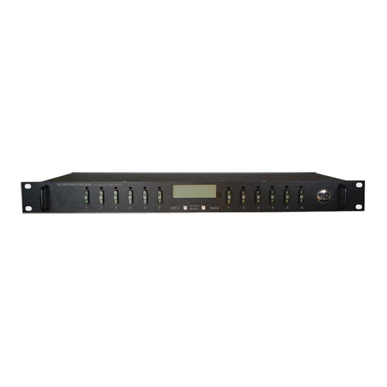
PRODUCT DESCRIPTION The ICT Dual Bus Distribution Panel provides two 100A (pk) bus inputs with six independently controlled and monitored output channels per bus in a compact 1U high chassis for 19 inch rack mounting. Over current protection for each output is available on the front panel in two configurations;... -
Page 5: Installation
ICT-CB15 CBI Electric BDG1ED-BOLXBS-1500X-1 ICT-CB25 CBI Electric BDG1ED-BOLXBS-2500X-1 Carling “M” series rocker handle circuit breakers with 0.25” tab terminals and current ratings up to 25A may also be used, consult ICT for suitable part numbers. Fuses: ICT Model Rating (80V) Mfg. - Page 6 Ensure the total power consumption of the loads does not exceed the 80A (continuous) rated capacity of each power bus Channel output breakers or fuses must not exceed 25A max rating for 12/24VDC systems, 15A max for nominal 48VDC systems Install only 80VDC rated fuses, 15 A max each for nominal 48Vdc systems ...
- Page 7 Shut off or disconnect all dc power sources before connecting or disconnecting wiring Use wire and connectors rated for the maximum load current and size of fuse or circuit breaker, and keep cable lengths as short as practical Carefully observe wiring polarity when making input and output connections ...
-
Page 8: Operation
Alarm 3-pin connector plugs, and installing in the back panel. Each Bus Alarm output will trigger for any fuse or breaker open, or other alarm related to any channel on that bus (Factory Default). Most alarm conditions can be masked off so that they will not trigger the Alarm output if required, using the web based graphical interface. -
Page 9: Lcd Display
Bus A Output 1-6 Bus B Output 1-6 LCD Display fuse open LED’s fuse open LED’s LCD Output Bus B Output 1-6 Bus A Output 1-6 select buttons fuses fuses Figure 2: Fuse Version Front Panel Energise each bus by closing the main external breaker or disconnect device on the bus input lines. - Page 10 Main Screen Line 1: The name of the panel (user configurable via the web based graphic interface, default is “ICT Dual Bus Panel”) Line 2: Displays the bus being monitored, Bus A or Bus B Line 3: The system voltage (voltage will blink if the voltage exceeds the Under-...
-
Page 11: Status Indicators And Alarms
Line 2: Name of the alarm (if configured, default is blank) Line 4: Alarm Status (ALARM if alarm is triggered, READY when not triggered) BUS A MENU BUS B MENU ICT DUAL BUS PANEL ICT DUAL BUS PANEL BUS: "A"... -
Page 12: Tcp/Ip Web Based Utility
Alarm Trigger Condition Channel Fuse Output Alarm Alarm (Fuse Contact vers) (Breaker vers) Fuse Open, or Fuse or breaker Breaker Off opens or is removed Bus Under- Bus V drops below change voltage UV threshold Bus Over- Bus V rises above the change voltage OV threshold... - Page 13 2. Enter the IP address of the panel in the address field of your browser as shown. If the panel is connected to a network with a DHCP server, the panel will be assigned an IP address automatically. To find the current address of your panel check the Network screen, line three, on the unit’s front panel LCD display.
-
Page 14: Status And Control
Click on any one of the blue buttons in the menu bar on the left side of the screen to select the desired page. Status and Control This page provides information on the voltage, current, and alarm status for each bus, along with the status of each channel output and the current being provided to each load. -
Page 15: Device Setup
Device Info Site Name: Enter a custom descriptive name for the panel Model: Displays the ICT model number for the panel Hardware: Displays the hardware version of the panel Date and Time Settings Current System Time: Displays the date and time used in the panel’s internal... - Page 16 Reverse Sequence Order: Checking this box will cause the power on sequence to run in reverse order with output channel 6 on first, ending with output 1, when the Enable Bus button is clicked on the Status and Control page. Network Watchdog: Watchdog Enabled: Checking this box will enable the watchdog feature, which will cause the unit to periodically ping up to two remote IP addresses...
-
Page 17: Bus Setup
Bus Setup Use this page to configure each bus. Select Bus A, or Bus B in the Select a Bus to Edit box to call up the settings for that bus. Click on the Save Settings button at the bottom of the page to save any changes you make. Bus A/B Settings: Bus Name: Enter a descriptive name for the selected bus if desired Bus A/B Under Voltage Alarm:... -
Page 18: Output Setup
Output Setup Use this page to configure the settings for each output channel on Bus A and Bus B. Select the output to be edited in the Select an Output to Edit box. Make any required changes, and then click on the Save Settings button at the bottom of the page to save any edits. -
Page 19: Network Setup
Load-Shedding Auto Recovery: Check this box to allow the output to be automatically reconnected when the bus voltage is above the Auto Recovery Threshold for at least 60s. The output must be manually re-enabled using the Output ON button on the Status and Control page if the Auto Recovery function is not enabled. - Page 20 IP Address: Specify a unique IP address for the unit. Subnet Mask: Specify the mask for the subnet the panel is located on Gateway: Specify the IP address of the default router (Gateway) used for connecting attached devices to different networks. Primary DNS: Specify the IP address of the Primary DNS Server for your network.
-
Page 21: E-Mail Setup
allow standard SNMP management software to connect to the SNMP agent running on the panel and read real time system information such as bus voltage, and channel currents. The panel can send SNMP traps to the external management software when an alarm or fault occurs. The information available from the SNMP agent is described in a MIB (Management Information Base) file, which can be downloaded from the panels Help page. - Page 22 SMTP Server: Enter the name or the IP address of your SMTP server used for sending outgoing e-mail. (e.g. “smtp.gmail.com”) SMTP Port: Enter the port used by your SMTP server. (Normally 25) SMTP Server requires SSL: Check this box if your SMTP server requires an encrypted SSL connection.
-
Page 23: Alarm Setup
Alarm setup Use this page to configure the set points of alarms to be monitored, and set the required actions when an alarm is triggered. Click on the Save Settings button at the bottom of the page to save any changes. Circuit Breaker (Fuse) Alarm: Activate Alarm Form-C Contact: Check this box to have the bus A alarm output trigger for any breaker or fuse on channel 1A to 6A opening, and... -
Page 24: Maintenance
Record your new password for future access! If the Administrator password is lost the unit must be reset to return the password to the blank default setting, causing loss of all other user settings. See the Password Reset section for more details. -
Page 25: Mobile Web App
MOBILE WEB APP Use the mobile version of the Status and Control page to monitor and control the panel with a smartphone web browser. Access the Mobile Web App by entering the address of the panel in the address field of your browser, followed by “/m”. (e.g. https://192.168.0.180/m) You will then be prompted for your user name and password, and logged into the following Status and Control screen: For improved security you should normally use a HTTPS (secures) connection... -
Page 26: Router Configuration
3. Press and release one of the output select buttons once to view the Network Status screen on the LCD. The factory default IP address for the panel will be displayed. ROUTER CONFIGURATION Use this section to set up a Distribution Panel with remote Internet access when located behind a router. - Page 27 (default UDP port is 9393) This step is optional if firmware upgrades are to be done locally. Router Port Forwarding Screen 5. Determine the WAN IP address of your router assigned by the ISP. With the example router this information is on the Status tab, listed as IP Address.
-
Page 28: Text Message Alarm Notifications
TEXT MESSAGE ALARM NOTIFICATIONS The panel can send alarm notifications as text messages to a cell phone by configuring the alarm e-mails to be sent to your mobile phone service provider. On the E-mail Setup page of the web based utility enter the address of your phone in the Recipient E-mail Address field. - Page 29 IP Address: 192.168.0.180 Subnet Mask: 255.255.255.0 Gateway: 192.168.0.1 If the HTTP port of the panel has been changed, you must append the new port number to the URL used to access the panel. (See the Network Setup section) See the Password Reset section for details on how to reset the port number to the factory default value.
-
Page 30: Product Specifications
PRODUCT SPECIFICATIONS Operating Voltage (either bus): 10VDC to 60VDC, or -10VDC to -60VDC Current Rating: 100A max, 80A continuous Bus A 100A max, 80A continuous Bus B 25A max, 20A Continuous per output (12/24V) 15A max, 12A Continuous per output (48V) Fuse Capacity (ICT200DF): 25A Max ATO 32V x 6 per bus (12/24V) 15A Max FKS-ATO 80V x 6 per bus (48V) - Page 31 Output Connector: 12 position cage clamp type per bus 10-22AWG, 5.22in-lb Alarm Connectors: Removable plug cage clamp type 16 – 28 AWG, 1in-lb screw torque Operating Temperature: -20°C to +60°C (Derate max bus current by 2% per degree C above 50°C) Weight: 7 lbs (3.2kg) Warranty:...
-
Page 32: Limited Warranty
The user of ICT products, which are to be used in life support applications as described above, assumes all risks of such use and indemnifies ICT against all damages.
Need help?
Do you have a question about the ICT200DF-12IRC and is the answer not in the manual?
Questions and answers