
Related Manuals for Velleman K8062


Summary of Contents for Velleman K8062
- Page 1 USB Controlled DMX interface Total solder points: 117 Difficulty level: beginner 1 2 3 4 5 advanced K8062 K8062 H8062IP-1...
- Page 2 CD with: test software, DLL for own developments, free DMX light player* * If not included, check our website http:\\www.velleman.be This device complies with Part 15 of the FCC Rules provided the enclosed instructions are followed to the letter. Use of the...
- Page 3 Assembly hints 1. Assembly (Skipping this can lead to troubles ! ) Ok, so we have your attention. These hints will help you to make this project successful. Read them carefully. 1.1 Make sure you have the right tools: A good quality soldering iron (25-40W) with a small tip.
- Page 4 3- Trim excess leads as close as possible to the solder joint AXIAL COMPONENTS ARE TAPED IN THE CORRECT MOUNTING SEQUENCE ! REMOVE THEM FROM THE TAPE ONE AT A TIME You will find the colour code for the resistances on our website: http://www.velleman.be/common/service.aspx...
- Page 5 Construction 1. Diode (check the polarity) 4. IC sockets D... CATHODE IC1 : 8P IC2 : 28P D1 : 1N4148 5. Capacitors 2. Zener diodes (check the polarity) c... ZD... CATHODE C1 : 33pF (33) C2 : 33pF (33) ...
- Page 6 Construction 8. USB connector 13. Push button * SK4 : USBB90 SW1 14. Battery holder * 9. Polyswitch resettable fuses 4mm M3 BOLT Mount the battery clip on the PCB FS1 : 3A /60Vdc using the 4mm M3 ...
- Page 7 17. IC’s check the position ! 18. CE/FCC Sticker Affix the supplied CE/FCC sticker on the bottom of the housing, see fig. 1.0. Velleman SFCC Tested to comply with FCC standards for home and office use IC1 : SN75176BP or MAX485 FIG.
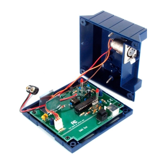
- Page 8 Assembly 20. Assembly Fix the PCB using 4 screws ( 2.9 x 6,5mm). Connect the wired connector to 3p header (SK3). If stand alone function is used, connect the battery to the connector and in- sert the battery in the battery compartment as indicated in fig. 5.0. ...
- Page 9 Software installation and test 21. Software installation Browse through the CD and open the K8062 folder. Check the appropriate PDF files for further information. The ‘light player’ software is installed in the folder by default: c:\program files\DMX This is a screen shot of the DMX_demo software, used tot test the unit or to make some simple shows.
- Page 10 23. PCB...
- Page 11 Schematic diagram 24. Diagram...
- Page 12 VELLEMAN NV Legen Heirweg 33, B-9890 GAVERE Belgium (Europe) Modifications and typographical errors reserved © Velleman Kit nv H8062IP - 2014 - ED1 (rev 6.0) 5 4 1 0 3 2 9 3 1 9 1 0 6...
Need help?
Do you have a question about the K8062 and is the answer not in the manual?
Questions and answers