Advertisement
Quick Links
Total solder points: 239
Difficulty level:
beginner 1
2
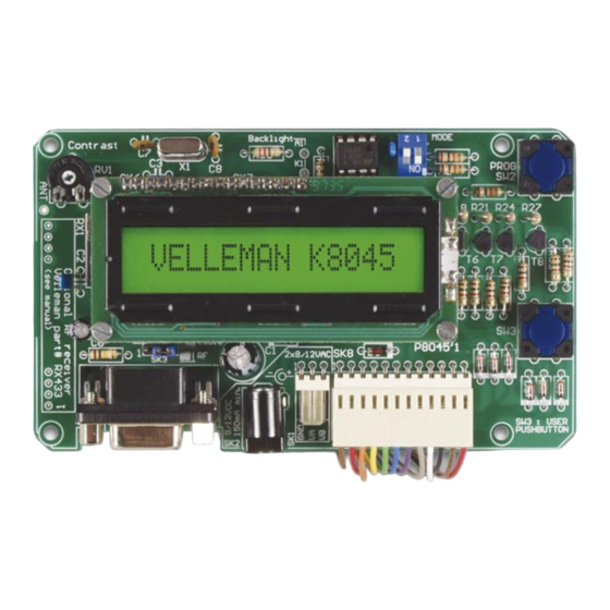
8 Input programmable messageboard
with LCD & serial interface
Features :
Add an LCD display to any low-tech application and make it look high-tech !
Replace up to 9 indicators or lamps by one single backlit LCD.
Recall messages simply by pressing a button.
Inputs accept dry contacts, open collectors and logic levels.
No programming skills required !
Store up to 9 sixteen-character messages in non-volatile EEPROM memory.
4 operating modes :
A default message can be entered and is displayed when no inputs are active.
Messages can be transferred to the K8045 from any PC or terminal.
Free message transfer software and source code for the K8045 is available
from www.velleman.be
Wireless data transfer between PC/terminal and K8045 is possible with op-
tional RX/TX433 modules.
1 on-board pushbutton available for your application.
Modifications reserved
ILLUSTRATED ASSEMBLY MANUAL
3
4
5
advanced
1) Display the status of all inputs simultaneously.
2) Display all active inputs.
3) Display active input with highest priority.
4) Display text messages in a 'tickertape'-fashion.
Specifications :
Inputs : 8 inputs (24Vmax)
Display : 16 character 1 line supertwist backlit LCD
Communication : RS232 2400/N/8/1 no handshaking
Power supply : 9-12VDC/150mA adapter or
2x9VAC/150mA transformer
Dimensions : 124x73x30mm max.
K8045
H8045IP-1
Advertisement

Related Manuals for Velleman K8045


Summary of Contents for Velleman K8045
-
Page 1: Specifications
4) Display text messages in a ‘tickertape’-fashion. A default message can be entered and is displayed when no inputs are active. Messages can be transferred to the K8045 from any PC or terminal. Free message transfer software and source code for the K8045 is available from www.velleman.be... - Page 2 Assembly hints 1. Assembly (Skipping this can lead to troubles ! ) Ok, so we have your attention. These hints will help you to make this project successful. Read them carefully. 1.1 Make sure you have the right tools: • A good quality soldering iron (25-40W) with a small tip.
- Page 3 Assembly hints 1.3 Soldering Hints : 1- Mount the component against the PCB surface and carefully solder the leads 2- Make sure the solder joints are cone-shaped and shiny 3- Trim excess leads as close as possible to the sol- der joint AXIAL COMPONENTS ARE TAPED IN THE CORRECT MOUNTING SEQUENCE !
- Page 4 C O L O R = 2 … 5 COLOR= 2...5 4K7= ( 4 - 7 - 2 - B ) 4K7= ( 4 - 7 - 0 - 1 - 1 ) CODICE CODIGO CODIGO VÄRI FÄRG FARVE- FARGE- FARB COLOUR CODIFI-...
- Page 5 Construction R10 : 1K (1 - 0 - 2 - B) 1. Jumperwire R11 : 1K (1 - 0 - 2 - B) R13 : 1K (1 - 0 - 2 - B) R14 : 1K (1 - 0 - 2 - B) R16 : 1K (1 - 0 - 2 - B) R17 : 1K...
- Page 6 Construction 7. Push buttons 11. Trim potentiometer RV... RV1 : 10K 12. 1/4W Resistors 8. DIP switch (check the color code) R... SW... R6 : 1K (1 - 0 - 2 - B) SW1 : DIP-2 R9 : 1K (1 - 0 - 2 - B) R12 : 1K (1 - 0 - 2 - B) 9.
- Page 7 Construction 14. Header 18. Quartz chrystal X... X1 : 4MHZ SK3 : 3p 19. IC’s 15. DC-jack IC1 : VK8045 (PIC16C57) IC2 : 24C02A 16. SUB-D connector 20. Shunt selection RS232 cable operation SK5 : SUB-D 9p female 17. Electrolytic capacitors Wireless link C...
- Page 8 LCD assembling 21. LCD assembling Cut the 20 pole connector to a 16 pole connector. Diagonal cutter FIG.1.0 Mount the 16 pole female connector. (see fig. 2.0) FIG.2.0 Mount 2x 6 pole male connectors. Pay attention : The four center connections of the LCD remain unused. Make sure that the longest pins aim towards the main PCB.
- Page 9 Assembly 22. Assembly Fit the display at the component side of the base PCB using four M2,5 bolts to- gether with four 15mm spacers. Fix the display using four M2,5 bolts at the sol- der side of the base PCB and check that the display is at right angles to the base PCB.
- Page 10 Connection 23. Connection 1. Hook-up when using an adapter : 9 –12VDC / 150mA 2. Hook-up when using a transformer 120 - 220 VAC Fuse : 250mA T TRANSFORMER 2 X 9VAC/150mA K8045...
- Page 11 A : antenna (30 - 40cm) R : 3K9 resistor (orange - white - red) The receiver is mounted on the left hand side of the K8045 board. Watch the position, the coils point to the LCD of the K8045. If you choose wireless opera-...
- Page 12 K8045. You can download free software from our website www.velleman.be, which allows you to transfer messages from the PC to your K8045 and which allows you to display messages on you K8045. You can also use a terminal or terminal emulation program to manually enter messages.
- Page 13 Message entering 26. Entering messages with a terminal program : The K8045 can store 9 sixteen-character messages, 1 for each input and a 9th which is displayed when no inputs are active. Briefly press SW2 ‘PROG’ to enter program mode The display shows ‘INPUT 1...9 / S / Q : ‘...
- Page 14 16 characters, the message scrolls to the left. An ID# can be assigned to the K8045 ranging from 0 to 9 (default : 0). This allows you to determine which K8045 will receive and display the message, which is handy for wireless link applications.
- Page 15 Options & examples 28. Options & examples Options : RF wireless link : ................. RX433/TX433 HQ supertwist LCD display : ............LCD1601ASL Application examples : Home alarm system : let your alarm system tell you what sensor has been triggered Replace car indicator lamps...
- Page 16 Options & examples Application with K8023 “Two wire 10-channel remote control”...
- Page 17 & DIAGRAMS...
- Page 19 Diagrams Diagram...
- Page 20 VELLEMAN COMPONENTS NV Legen Heirweg 33 9890 Gavere Belgium Europe Info & support: www.velleman.be Modifications and typographical errors reserved © Velleman Components NV H8045IP - 2002 - ED1...
Need help?
Do you have a question about the K8045 and is the answer not in the manual?
Questions and answers