
Related Manuals for HAI Omnistat RC-120


Summary of Contents for HAI Omnistat RC-120
- Page 1 O M N I S T A T ELECTRONIC COMMUNICATING THERMOSTAT Installation Manual RC-120 Two Stage Heat/Cool 2 Stage Heat / 2 Stage Cool Document Number 13I00-7 January, 1997...
- Page 2 Copyright © 1997 Home Automation, Inc. All Rights Reserved...
-
Page 3: Table Of Contents
CONTENTS ........DESCRIPTION ........INSTALLATION . -
Page 4: Description
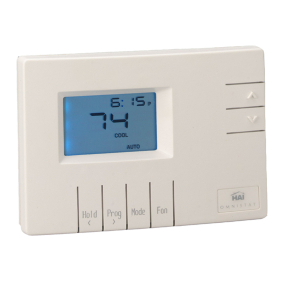
DESCRIPTION The RC-120 is a precision digital thermostat designed for 24 VAC two stage heating and cooling systems. It has the capability of being controlled both locally and by remote control. It offers programmability, stand alone operation, and robust, optically isolated communications with automation systems, utility control systems, and personal computers. -
Page 5: Location
LOCATION When replacing an existing thermostat, install the RC-120 in the same location. If the existing location doesn't meet the following criteria, choose a new location to mount the RC-120. When choosing a location for the thermostat: 1. Ensure that the thermostat is mounted about 5 feet above the floor and is at least 2 feet from an outdoor wall. -
Page 6: Mounting
MOUNTING When mounting the RC-120, grasp the thermostat by the sides, avoiding the keys, and unsnap the base from the face. Holding the base to the wall so that the word "TOP" is upright and facing you: 1. Mark the two mounting holes on the wall using a pencil. 2. - Page 7 Connect each wire to the terminal strip on the thermostat base per the wiring diagram for your system application - See Figures 4 - 5. Form the thermostat wiring so that the cable lies flat between the terminal strip and the center of the thermostat base - See Figure 2. Figure 2 - Forming thermostat wiring If a remote system is being used with the thermostat, connect the...
- Page 8 Align the tabs of the thermostat face with the slots of the thermostat base. Gently push the thermostat face into the thermostat base locking it into place - See Figure 3. SLOT FACE TEMPERATURE BASE WALL SENSOR Figure 3 - Mounting thermostat face to thermostat base Note: Be sure that the thermostat temperature sensor is standing up, and...
-
Page 9: Typical Wiring Diagrams
TYPICAL WIRING DIAGRAMS CAUTION 1. Be sure to disconnect the power to the control transformer before removing or installing thermostat. 2. Do not short cooling or heating relays, or fan relay... even momentarily. This will blow a non-replaceable fuse. 3. Do not attempt to hook up to live circuits. An accidental connection to a component on the thermostat circuit board could cause damage to the thermostat. - Page 10 FIGURE 5...
-
Page 11: Power Up
POWER UP 1. Double check wiring, be sure that there are no stray wires or wire strands at the connections. 2. It is not necessary to connect the remote system (COMM) cable at this time. 3. Connect power to the control transformer and system. The display will show all segments for about 5 seconds. -
Page 12: Disable Keys
DISABLE KEYS The keys on the thermostat can be disabled to prevent anyone from controlling the thermostat locally. To disable the keys, solder a wire jumper across the two holes on the circuit board as shown in Figure SOLDER WIRE JUMPER HERE FIGURE 6 INSTALLER SETUP... -
Page 13: Item Number
The thermostat will automatically exit Setup mode after 20 seconds of no key activity. To enter the Installer Setup, set Mode to "OFF". After 10 seconds, press the Prog key three times (day will flash), then press the Fan key. ITEM NUMBER VALUE The word "default"... -
Page 14: System Options
02 System options The thermostat can be configured with the following system options: 0 Auto changeover no fan with heat 1 Auto changeover fan on with heat 4 Manual changeover no fan with heat 5 Manual changeover fan on with heat 12 Heat only no fan with heat 13 Heat only... -
Page 15: Calibration Offset
Add 16 to each setting to disable the clock and filter reminder displays. This may be appropriate for non-programmable and commercial use where the time display is not desired. 04 Calibration offset This item is used to raise or lower the current temperature reading by 1 degree Fahrenheit or 1/2 degree Celsius. -
Page 16: Heating Minimum On/Off Time
Setting Cycles per hour (maximum) The recommended setting is 8 minutes. A higher setting may be appropriate for buildings with low heat loss/gain. The default setting is 8. 12 Heating minimum on/off time (minutes) Same as Cooling minimum on/off time, for the heating system. The default setting is 8. -
Page 17: Owner's Manual
(1 = - 29 to 59 = + 29 - Seconds per day - 30 = No change) The default setting is 30. Note: If an HAI automation system is being used, the controller system time is sent to the thermostat every minute. This adjustment will have no effect. -
Page 18: Quick Reference Setup Guide
QUICK-REFERENCE SETUP GUIDE This table displays each Installer Setup item with it's default setting. The column labeled "CURRENT" can be used to write down the current settings if any changes are made to the default settings. Item Number Description Default Current Address Communication mode System options... -
Page 19: Remote System Wiring Diagrams
Run a 3 (or 4) conductor wire from the HAI system to the thermostat location. All thermostats on an Omni, OmniPro, and Aegis controller are connected to Zone 16 and Output 8. - Page 20 Additional thermostats are connected in parallel. They may be connected in home-run or daisy chain configuration. REMOTE DAY/NIGHT SETBACK SWITCHES The thermostat can be connected to a remote system or remote switch. A signal can be sent from the remote location to change the thermostat temperature settings from the "DAY"...
-
Page 21: Troubleshooting Tips
TROUBLESHOOTING TIPS SYMPTOM ACTION TO TAKE Thermostat Dead 1. Check power to the thermostat 2. Check wiring diagrams 3. Check thermostat temperature sensor Thermostat will not operate with a damaged temperature sensor SYMPTOM ACTION TO TAKE Fan, Heat, Or Cool 1. - Page 22 SYMPTOM ACTION TO TAKE Temperature 1. Allow 30 minutes for thermostat to Reading Incorrect adjust to room temperature 2. Adjust calibration offset 3. Change setup option to display F or After installation, allow the thermostat up to 30 minutes for an accurate temperature reading SYMPTOM ACTION TO TAKE...
Need help?
Do you have a question about the Omnistat RC-120 and is the answer not in the manual?
Questions and answers