Advertisement
Quick Links
Please read all instructional literature carefully and thoroughly before starting. Refer to the final page for the listing of Recommended
Practices, Liabilities and Warranties.
GENERAL
MIsuse of ThIs producT May cause explosIon and personal
Injury. These InsTrucTIons MusT be Thoroughly read and
undersTood before unIT Is InsTalled.
ThIs eQuIpMenT Is suITable for class I, dIVIsIon 2,
groups a,b,c,d; class II, dIVIsIon 2, groups f and g; class III;
or non-haZardous locaTIons only.
These producTs do noT haVe any fIeld replaceable parTs.
any subsTITuTIon of coMponenTs May IMpaIr suITabIlITy for
class I, dIVIsIon 2
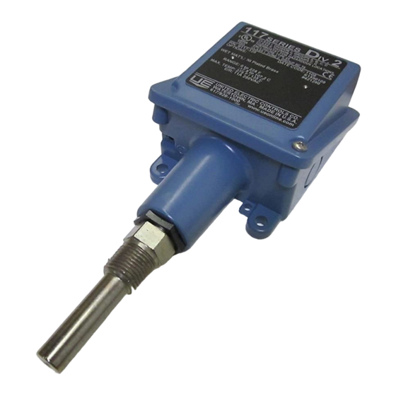
Types B117 (Immersion Stem)
The 117 series temperature switch utilizes a liquid filled sensor which
expands or contracts against a bellows to detect a temperature change.
The response, at a pre-determined set point, actuates or deactuates a
spdT or dpdT snap-acting switch, converting the temperature signal into an
electrical signal. control set point is adjusted by turning an internal dial (see
adjustment - part II).
Types E117 (Bulb & Capillary)
The 117 series temperature switch utilizes a liquid-filled sensing bulb which
hydraulically transmits temperature change to a bellows. The response, at
a pre-determined set point, actuates or deactuates a spdT or dpdT snap-
acting switch, converting the temperature signal into an electrical signal.
control set point is adjusted by turning an internal dial (see adjustment -
part II).
MaxIMuM TeMperaTure: The hIghesT TeMperaTure To whIch a
sensIng eleMenT May be occasIonally exposed To wITh-
ouT adVersely affecTIng seT poInT calIbraTIon and repeaT-
abIlITy. MaxIMuM TeMperaTure sTaTed In lITeraTure and on
naMeplaTe MusT neVer be exceeded, eVen by TeMperaTure oVer-
shooTs In The sysTeM. occasIonal operaTIon of unIT up To Max.
TeMperaTure Is accepTable (e.g., sTarT-up, TesTIng). conTInuous
operaTIon should be resTrIcTed To The desIgnaTed adjusTable
range.
please refer to product bulletin for product specifications. product bulletins
may be found at www.ueonline.com.
Part I - Installation
MOUNTING
warnIng: explosIon haZard - do noT dIsconnecT eQuIpMenT
unless power has been swITched off or The area Is Known
To be non-haZardous.
InsTall unIT where shocK, VIbraTIon and TeMperaTure fluc-
TuaTIons are MInIMal. do noT MounT unIT In aMbIenT TeMper-
aTures exceedIng publIshed lIMITs. 100 serIes TeMperaTure
swITches can be MounTed In any posITIon, proVIded The
elecTrIcal conduIT Is noT facIng up. orIenT unIT so ThaT
MoIsTure Is preVenTed froM enTerIng The enclosure.
always hold a wrench on The TeMperaTure housIng hex
when MounTIng unIT. do noT TIghTen by TurnIng enclosure.
ThIs wIll daMage sensor and weaKen soldered or welded
joInTs.
117 Series
Temperature Switch
Types B117, E117
Tools Needed
adjustable wrench
flasthead screwdriver
hammer (for alternate wire knockouts)
U N I T E D E L E C T R I C
C O N T R O L S
Installation and Maintenance
Instructions
Mount the unit via the (2) 1/4" screw clearance holes on the enclosure (see
Mounting dimensions).
for remote mounting, fully immerse the bulb and 6" capillary in the control
zone. for best control, it is generally desirable to place the bulb close to the
heating or cooling source in order to sense temperature fluctuations quickly.
be sure to locate the bulb so it will not be exposed to temperature beyond
the instrument range limits.
WIRING
dIsconnecT all supply cIrcuITs before wIrIng unIT.
wIre unITs accordIng To naTIonal and local elecTrI-
cal codes. MaxIMuM recoMMended wIre sIZe Is 14 awg.
The recoMMended TIghTenIng TorQue for fIeld wIrIng
TerMInals Is 7 To 17 In-lbs.
elecTrIcal raTIngs sTaTed In lITeraTure and on naMeplaTe
should neVer be exceeded. oVerload on a swITch can
cause faIlure on The fIrsT cycle.
remove the two screws retaining the cover and cover gasket. a 1/2" npT
conduit connection is provided on the left hand side of the enclosure. Two
cast-in 7/8" diameter knock outs for electrical conduits are located on the
side and back of enclosure (see dimensional drawings, opposite page).
These can easily be knocked out by placing a blade of a screwdriver in
groove and tapping sharply with a hammer. The terminal block terminals are
clearly labeled "common", "normally open" and "normally closed." for units
supplied with dpdT, all terminals are labeled and the following color coding
applies.
common
normally closed
normally open
grounding screw and clamp (cast in symbol) are provided. Keep the wire as
short as possible to prevent interference with the plunger.
Part II - Adjustments
To change set point, turn dial and align with pointer.
Types B117 and E117 with dial knob controls are factory calibrated for
maximum accuracy at the midpoint of the scale.
Re-calibration
To re-calibrate, turn dial to desired set point. If the actual temperature and set point
temperature do not agree, turn the 3/16" hex fine adjustment screw to the left (clock-
wise) to raise and to the right (counter-clockwise) to lower temperature setting.
IMT117-07
www.ueonline.com
SPDT
DPDT
swT1
swT2
Violet
Violet
yellow
black
black
red
blue
blue
orange
IMT117-07
Advertisement

Related Manuals for United Electric Controls 117 Series


Summary of Contents for United Electric Controls 117 Series
- Page 1 MaxIMuM recoMMended wIre sIZe Is 14 awg. Types B117 (Immersion Stem) The recoMMended TIghTenIng TorQue for fIeld wIrIng The 117 series temperature switch utilizes a liquid filled sensor which TerMInals Is 7 To 17 In-lbs. expands or contracts against a bellows to detect a temperature change.
- Page 2 Dimensions RECOMMENDED PRACTICES AND WARNINGS United Electric Controls Company recommends careful consideration Dimensional drawings for all models may be found at www.ueonline.com. of the following factors when specifying and installing UE pressure and temper- ature units. Before installing a unit, the Installation and Maintenance instruc- tions provided with unit must be read and understood.