
Related Manuals for Daikin TSTATD1100-2


Summary of Contents for Daikin TSTATD1100-2
- Page 1 TSTATD1100-2 RESIDENTIAL Digital Thermostat Non-Programmable Owner's Manual Installation Instructions Residential Use...
-
Page 2: Table Of Contents
Table of Contents Safety Warnings ..............3 Front Panel ................4 Dispay ..................5 Normal Operation ..............6 Fahrenheit or Celsius ............7 Preparation ................8 Remove Old Thermostat ............9 Battery Replacement ............10 Wire Connections ..............11 Sample Wiring Diagrams ...........12 Jumper Configuration ............18 Test Operation ..............22 Troubleshooting ..............23 Warranty ................24... -
Page 3: Safety Warnings
Safety Warnings Follow Installation Instructions carefully. DISCONNECT POWER TO THE HEATER - AIR CONDITIONER BEFORE REMOVING THE OLD THERMOSTAT AND INSTALLING THE NEW THERMOSTAT. The two Alkaline “AA” batteries must be replaced at least once every 12 months to ensure proper operation. The Low Battery icon will appear on the display when it is time to replace the batteries. -
Page 4: Front Panel
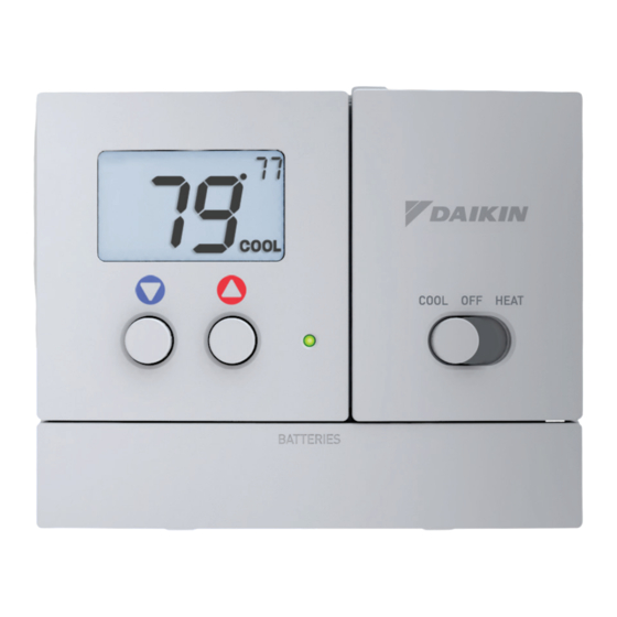
Front Panel DISPLAY FAN SWITCH On or Auto HEAT AUTO COOL HEAT BATTERIES BATTERY DOOR COOLER & MODE SWITCH Cool, Off, or Heat WARMER BUTTONS BI-COLOR LED Heat or Cool demand indicator when system powered: Red = Heat Green = Cool... -
Page 5: Dispay
Display SET TEMP HEAT COOL BATTERY Heat and Cool indicators. In normal operation, Heat or Cool appears, depending on the Mode Switch position. When heat or cool is energized, the Heat or Cool indicator will flash. Current room temperature. Desired set temperature indicator. When this indicator is on, the large numbers represent the desired room temperature. -
Page 6: Normal Operation
Normal Operation FAN SWITCH On or Auto HEAT AUTO COOL HEAT BATTERIES COOLER & WARMER MODE SWITCH Cool, Off, or Heat BUTTONS Operation Select Cool or Heat with the Mode Switch. Normally leave the fan switched to Auto. In Fan Auto, the fan will turn on only with a heat or cool demand. -
Page 7: Fahrenheit Or Celsius
Fahrenheit or Celsius HEAT AUTO COOL HEAT BATTERIES COOLER & WARMER MODE SWITCH Cool, Off, or Heat BUTTONS Operation Select Off with the Mode Switch. Press and hold the COOLER and WARMER buttons at the same time until the temperature is displayed in degrees Celsius. Repeat this process to display the temperature in degrees Fahrenheit. -
Page 8: Preparation
Preparation • Proper installation of the thermostat will be accomplished by following these step by step instructions. If you are unsure about any of these steps, call a qualified technician for assistance. • These tools will be required: Wire Cutter Flat Blade &... -
Page 9: Remove Old Thermostat
Remove & Replace Old Thermostat • Remove the cover of the old thermostat. If it does not come off easily check for screws. • Loosen the screws holding the thermostat base or subbase to the wall, and lift away. • Disconnect the wires from the old thermostat. Tape the ends of the wires as you disconnect them, and mark them with the letter of the terminal for easy reconnection to the new thermostat. -
Page 10: Battery Replacement
Battery Replacement The batteries are easily accessible from the battery door located on the bottom front of the thermostat (fig. 1). To open the battery slot, pull out on the battery door (fig. 1) and swing down (fig. 2). FIG. 1 FIG. -
Page 11: Wire Connections
Remove this jumper to control dual transformer systems. Thermal Insulating Sheet A label is provided on the backplate that prevents drafts originating inside MODEL: TSTATD1100-2 97061606 4Z95 USE SIZE “AA” the wall from entering the thermostat. MADE IN CHINA... -
Page 12: Sample Wiring Diagrams
Sample Wiring Diagrams Gas or Electric Heat 4 Wire, 1 Stage Cooling, 1 Stage Heating Residential Gas or Electric Heat, Electric Cool, split systems & package units. For jumper configuration see pages 18 and 19. Common wire optional C O/B Y W G RC RH Factory installed jumper between RC and RH... - Page 13 Sample Wiring Diagrams Gas or Electric Heat 4 Wire, 1 Stage Cooling, 1 Stage Heating-Heat Pump with O reversing valve Residential Heat Pumps, split systems & package units, with no auxiliary heat For jumper configuration see page 20. Common wire optional C O/B Y W G RC RH Factory installed jumper between...
- Page 14 Sample Wiring Diagrams Gas or Electric Heat 4 Wire, 1 Stage Cooling, 1 Stage Heating-Heat Pump with B reversing valve. Residential Heat Pumps, split systems & package units, with no auxiliary heat. For jumper configuration see page 21. Common wire optional C O/B Y W G RC RH Factory installed jumper between...
- Page 15 Sample Wiring Diagrams Gas or Electric Heat 3 Wire, 1 Stage Heating Residential Gas or Electric Heat units with a separately controlled fan. For jumper configuration see pages 18 and 19. Common wire optional C O/B Y W G RC RH Factory installed jumper between RC and RH...
- Page 16 Sample Wiring Diagrams Gas or Electric Heat 2 Wire, 1 Stage Gas Heat Residential Gas or Millivolt units. For jumper configuration see page 18. Common wire optional C O/B Y W G RC RH Factory installed jumper between RC and RH 2 Conductor 18 to 22 gauge unshielded cable from the thermostat to the equipment.
- Page 17 Sample Wiring Diagrams Gas or Electric Heat Dual Transformer 5 Wire, 1 Stage Cooling, 1 Stage Heating Residential Gas or Electric Heat, Electric Cool, split systems & package units. For jumper configuration see pages 18 and 19. Common wire optional C O/B Y W G RC RH Remove the factory installed...
-
Page 18: Jumper Configuration
Jumper Configuration Cooling and Gas Heating Residential Gas, Electric Cool, split systems & package units. ASDF ASDF ASDF GAS/ELEC ELEC Jumper #1 (J1) should be set for GAS (FAN) and Jumper #2 (J2) should be set for GAS for for typical gas furnace heating with electric cooling. Jumper #3 (J3) is not used. - Page 19 Jumper Configuration Cooling and Electric Heating Residential Electric Heat units with a separately controlled fan. ASDF ASDF ASDF ELEC GAS/ELEC ELEC Jumper #1 (J1) should be set for ELEC (FAN) and Jumper #2 (J2) should be set for GAS for typical gas furnace heating with electric cooling. Jumper #3 (J3) is not used.
- Page 20 Jumper Configuration Cooling and Electric Heating - Heat Pump with O reversing valve. Residential Heat Pumps, split systems & package units, with no auxiliary heat. ASDF ASDF ASDF ELEC GAS/ELEC ELEC Jumper #1 (J1) should be set for ELEC (FAN), Jumper #2 (J2) should be set for HP, and Jumper #3 (J3) should be set for O for typical heat pump operation.
- Page 21 Jumper Configuration Cooling and Heating - Heat Pump with B reversing valve. Residential Heat Pumps, split systems & package units, with no auxiliary heat. ASDF ASDF ASDF ELEC GAS/ELEC ELEC Jumper #1 (J1) should be set for ELEC (FAN), Jumper #2 (J2) should be set for HP, and Jumper #3 (J3) should be set for B for typical heat pump operation.
-
Page 22: Test Operation
Test Operation • Turn on the power to the Heating/Air Conditioning system. • On the thermostat, slide the Mode Switch to HEAT. Press the COOLER or WARMER button until the set temperature is 10 degrees above room temperature. The HVAC unit should energize in the heating mode (Page 6). -
Page 23: Troubleshooting
Troubleshooting • SYMPTOM: The slide switches on the thermostat are very difficult to move. CAUSE: The backplate of the thermostat is screwed too tightly into a wall that is not perfectly flat. REMEDY: Loosen the screws holding the thermostat into the wall. •... -
Page 24: Warranty
Installer Name __________________________________________________________________ Installation Date ________________________________________________________________ Model # _______________________________________________________________________ Serial # ________________________________________________________________________ For further information about this warranty, contact Daikin Consumer Affairs at (877) 254-4729 or by mail to 7401 Security Way, Houston, Texas 77040. - Page 25 Battery Stat P/N TSTATD1100-2 Tested to Comply with FCC Standards FOR HOME OR OFFICE USE 4Z95 Printed on recycled paper. P/N 88-993 Rev. 1 12/13...
Need help?
Do you have a question about the TSTATD1100-2 and is the answer not in the manual?
Questions and answers