Advertisement
Quick Links
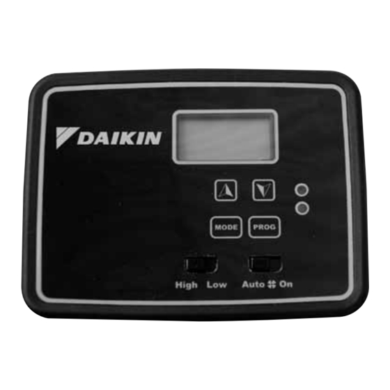
Programmable Electronic Thermostat
7-Day Programmable, Auto Changeover, Fan Speed Control, Hardwire
Daikin P/N (66881 1 101)
• 7-Day Programmable
• Single Stage Heat Pump/Non-Heat Pump Systems
• Backlit Display
• Single Stage Heat/Cool Systems
• Two Speed Fan Control
• Field Calibration
• Auto Changeover
• Button Lockout Function
• SimpleSet™ Programming
• Remote Temperature Sensor Capability
• Title 24 Compliant / No Batteries Required
• Relay Outputs (minimum voltage drop in thermostat)
• Ideally Suited for:
– Residential (New Construction/Replacement)
– Light Commercial
Installation, Operation & Application Guide
Version C: 06-30-15
Specifications
Electrical Rating: • 24 VAC (18 to 30 VAC)
• 3 amp maximum total load
• 1 amp maximum per terminal
Temperature control ranges: 45°F to 90°F Accuracy: ± 1°F
System configurations: 1-stage heat, 1-stage cool, heat pump, gas, oil, electric
Timing: Anti-short Cycle: 5 minutes
Backlight Operation: 10 seconds
Terminations: C, RH, RC, W, Y, B, O, G1, G2, S1, S2
Important Safety Information
Always turn off power at the main power supply before installing, cleaning, or removing thermostat.
• This thermostat is for 24 VAC applications only; do not use on voltages over 30 VAC
• Do not short across terminals of gas valve or system control to test operation; this will damage your thermostat
and void your warranty
• All wiring must conform to local and national electrical and building codes
• Do not use air conditioning when the outdoor temperature is below 50 degrees; this can damage your A/C system
and cause personal injuries
• Use this thermostat only as described in this manual
Package Contents/Tools Required
Package includes: Daikin 668811101 programmable thermostat + Operation & Application Guide.
To Remove Existing Thermostat
ELECTRICAL SHOCK HAZARD – Turn off power at the main service panel by removing the fuse or
switching the appropriate circuit breaker to the OFF position before removing the existing thermostat.
1. Turn off power to the heating and cooling system by removing the fuse or switching the appropriate circuit breaker
off.
2. Remove old thermostat. This should expose the wires.
3. Label the existing wires before removing wires.
4. After labeling wires, remove wires from wire terminals.
5. Refer to the following section for instructions on how to install this thermostat.
To Install Thermostat
ELECTRICAL SHOCK HAZARD – Turn off power at the main service panel by removing the fuse or
switching the appropriate circuit breaker to the OFF position before removing the existing thermostat.
IMPORTANT: Thermostat installation must conform to local and national building and electrical codes and
ordinances.
1. Turn off power to the heating and cooling system by removing the fuse or switching the appropriate circuit breaker
off.
2. Insert stripped, labeled wires in matching wire terminals. See "Wiring Diagrams" section of this manual.
Be sure exposed portion of wires does not touch other wires.
3. Tighten screws on terminal block. Gently tug wire to be sure of proper connection. Double check that each wire is
connected to the proper terminal.
4. Remove unused Gas/Electric jumper. Keep gas for oil or gas systems. Keep electric for heat pumps or electric
heat systems.
5. Replace thermostat by snapping it in place.
6. Turn on power to the system at the main service panel.
7. Test thermostat operation as described in "Testing the Thermostat".
Remote Sensor Installation (Optional)
1. Remove cover from remote sensor housing.
2. Select an appropriate location for mounting the remote sensor.
3. Mount remote sensor unit using hardware provided.
4. Install two strand shielded wire between remote sensor and thermostat. Shielded wire must be used. Do not run
remote sensor wire in conduit with other wires.
• Wire 1 should run between the S1 terminal on the thermostat and the S1 terminal on the remote sensor
• Wire 2 should run between the S2 terminal on the thermostat and the S2 terminal on the remote sensor
• Connect the shielding of the wire to the S2 terminal on the thermostat
5. Disable the main sensor (R12) on the thermostat by cutting it from the circuit board.
WARNING
WARNING
WARNING
WARNING
Wiring Diagram
6-Wire,
Configuration Mode
The configuration mode is used to set the Daikin 668811101 thermostat to match your heating/cooling system. The
Daikin 668811101 thermostat functions with heat pump, air conditioning, gas, oil or electric heat systems.
1. To enter the configuration mode, simultaneously hold down the
the Daikin 668811101 thermostat is in OFF mode.
2. Press the
or
button to change settings within each screen.
3. Press the PROG button to advance to the next screen.
Note: The MODE button will return you to the previous screen.
4. To exit configuration mode, hold the PROG button for 6 seconds.
Configuration Mode Settings
1. Temperature scale (F or C) – Choose Fahrenheit or Celsius.
Press the
or
button to select.
Press the PROG button to advance to the next screen.
2. Differential (1°F - 5°F) (1°C - 3°C) – Set the number of degrees between your "turn on"
temperature and your "setpoint" temperature.
Press the
or
button to set differential value.
Press the PROG button to advance to the next screen.
3. Deadband (1°F - 9°F) (1°C - 5°C) – Set the minimum number of degrees between
your heating system activation and your cooling system activation.
Press the
or
button to set deadband value.
Press the PROG button to advance to the next screen
4. Heat pump – Press the
or
button to configure as heat pump, or non-heat pump
system.
• ON = Heat pump system – 4 minute time delay with heat and cool
• OFF = Non-heat pump system – 4 minute time delay with cool only
Press the PROG button to advance to the next screen
5. Lockout (0-8°, NITE, COOL-HEAT) – Select the number of degrees set temperature
can be changed during keypad lockout or select to lockout during NITE period only.
COOL-HEAT lockout allows adjustment of the set temperatures to the maximum heat set
temperature selected in Step 6 and minimum cool set temperature selected in Step 7.
Note: The mode cannot be changed when the thermostat is locked.
Press the
or
button to select.
Press the PROG button to advance to the next screen
6. Maximum Heat Setpoint (45°F - 90°F) (7°C - 32°C)
Adjust to control the maximum heat set temperature allowed.
Press the
or
button to select.
Press the PROG button to advance to the next screen
7. Minimum Cool Setpoint (45°F - 90°F) (7°C - 32°C)
Adjust to control the minimum cool set temperature allowed.
Press the
or
button to select.
Press the PROG button to advance to the next screen
8. Room temperature offset (+9°F to - 9°F) (+5°C to -5°C).
Adjust to calibrate displayed room temperature to match actual room temperature.
Press the PROG button to advance to the next screen.
9. Maximum compressor cycles allowed per hour (d, 2-6).
– – = as many as needed, 2-6 = maximum cycles/hour
Press the PROG button to advance to the next screen.
10. Status indicator light (ON, OFF).
Press the
or
button to select.
To exit configuration mode, press the PROG button for 6 seconds.
Starting the Thermostat
Note: First button press activates backlight only.
1. Move the Fan Auto/On switch to the Auto position.
2. Press the MODE button to enter desired operating mode.
3. Press PROG to select program or non-program option.
Testing the Thermostat
Once the thermostat is installed, it should be thoroughly tested.
Do not energize the air conditioning system when the outdoor temperature is below 50 degrees.
It can result in equipment damage or personal injury.
Cool Test
1. Press mode button until cool mode is displayed.
2. Adjust set temperature so it is 5 degrees below room temperature.
3. Air conditioning should come on. Green LED turns ON.
4. Adjust the set temperature 2 degrees above the room temperature and the A/C should
turn off. There may be a fan delay on your system.
Note: T here is a four-minute time delay to protect the compressor after it turns off.
Heat Test
1. Press mode button until heat mode is displayed.
2. Adjust the set temperature so it is 5 degrees above the room temperature.
3. Heat should come on. Red LED turns ON.
4. Adjust the set temperature 2 degrees below the room temperature and the heat
should turn off. There may be a fan delay on your system.
Note: For heat pumps, there is a four-minute delay to protect your compressor.
Fan Test
1. Slide fan switch to ON position.
Indoor fan turns ON.
2. Slide fan switch to Auto position.
Indoor fan turns OFF.
and
buttons while
ON
CAUTION
Advertisement

Related Manuals for Daikin 668811101


Summary of Contents for Daikin 668811101
- Page 1 Wiring Diagram Programmable Electronic Thermostat 7-Day Programmable, Auto Changeover, Fan Speed Control, Hardwire Daikin P/N (66881 1 101) 6-Wire, • 7-Day Programmable • Single Stage Heat Pump/Non-Heat Pump Systems • Backlit Display • Single Stage Heat/Cool Systems • Two Speed Fan Control • Field Calibration • Auto Changeover • Button Lockout Function • SimpleSet™ Programming • Remote Temperature Sensor Capability • Title 24 Compliant / No Batteries Required • Relay Outputs (minimum voltage drop in thermostat) • Ideally Suited for: – Residential (New Construction/Replacement) – Light Commercial Configuration Mode Installation, Operation & Application Guide The configuration mode is used to set the Daikin 668811101 thermostat to match your heating/cooling system. The...
- Page 2 6. Press the or button to change period of day. exiting program setup), configuration and program settings are unchanged. 7. Press the PROG button to advance to the next screen. • Set time is displayed 8. Press the or button to change set time. 9. Press the PROG button to advance to the next screen. Daikin Training and Development Note: Transitions required after 11:59 PM must be programmed in the next day’s Now that you have made an investment in modern, efficient Daikin equipment, its care should be a high priority. For MORN transition. training information on all Daikin HVAC products, please visit us at www.DaikinApplied.com and click on Training, or call 540-248-9646 and ask for the Training Department. • Heat temperature is displayed (45°F to 90°F) 10. Press the or button to adjust heat set temperature.
Need help?
Do you have a question about the 668811101 and is the answer not in the manual?
Questions and answers