
Related Manuals for Efco Swaploader SL-330


Summary of Contents for Efco Swaploader SL-330
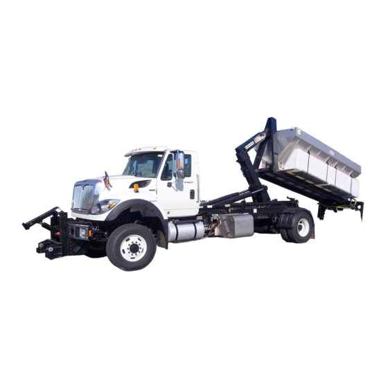
- Page 1 Model SL-330 Parts and Operations Manual Hoist Serial Number: ____________________...
- Page 3 WARRANTY REGISTRATION FORM HOIST INFORMATION MODEL: Signature: SERIAL NO.: Date Installed: Date Inspected: VEHICLE INFORMATION Manufacturer: Model: Year: Wheel Base: VIN: PTO Type: PTO Ratio: DISTRIBUTOR INFORMATION Company Name: Sales Person’s Name: Address: City, State & Zip: Phone: The unit has been checked and serviced according to SwapLoader’s Pre-delivery Check List. The proper mechanical operation of the unit as described in the written Parts &...
- Page 5 PRE-DELIVERY CHECK LIST INSPECTOR’S INFORMATION Inspected By: Signature: Distributor: Date Installed: Customer: Date Inspected: I. COMPONENT INFORMATION Hoist Model: Hoist Serial No.: Chassis VIN: Chassis Make & Model: Chassis GVWR: Distance from rear of cab to the centerline Chassis CA / CT: of rear axle/tandem.
- Page 6 III. CONTROLS Controls easy to operate from driver’s seat. Movement of controls correct, per installation instructions. IV. HYDRAULIC INSTALLATION Correct hydraulic oil level in reservoir, per installation instructions. Inspected for leaks. Any abnormal noise during hoist operation? If yes, please describe: With engine operating @ 1,000 RPM, record the following information: Cycle time for dump mode: Seconds Up...
-
Page 9: Table Of Contents
TABLE OF CONTENTS INTRODUCTION PARTS LIST Letter to Customer Base Assembly Warranty Statement Mainframe Subassembly Safety Suggestions Rear Pivot Subassembly Telescopic Jib Subassembly INSTALLATION Mast Lock (Safety Latch) Assembly Hoist Installation Kit Assembly Initial Inspection Manual Control Assembly, 2 Section Hoist Installation Hyd. - Page 11 INTRODUCTION...
- Page 13 SWAPLOADER U.S.A., LTD. TO THE CUSTOMER Your new SwapLoader Hoist was carefully designed and manufactured to give years of dependable service. To keep it operating efficiently, read the instructions in this manual thoroughly. It contains detailed descriptions and instructions for the efficient operation and maintenance of your SwapLoader.
- Page 14 SWAPLOADER, U.S.A., LTD. 1800 N.E. BROADWAY, DES MOINES, IOWA 50313 LIMITED WARRANTY STATEMENT Effective September 1, 2009 SwapLoader U.S.A., Ltd., (SwapLoader), warrants to the original purchaser of any new SwapLoader product sold by an authorized SwapLoader distributor or service center, that such products are free of defects in material and workmanship. All SwapLoader products with an original factory invoice date of September 1, 2009 or later qualify for warranty as defined in this Limited Warranty Statement.
-
Page 15: Safety Suggestions
SAFETY SUGGESTIONS Do not operate or service this equipment until you have been properly trained and instructed in its use and have read the operation and service manual. Do not operate this equipment on uneven ground. Do not drive with the hoist in the dump position or with the hook to the rear. - Page 16 Make sure work area is clear of people and obstacles prior to dumping or unloading containers. SwapLoader strongly recommends that a back up alarm be installed on the truck chassis. The operation of the hook hoist is that the truck is backed up to the body to pick it up and so there is a potential pinch point between the body and the hook.
- Page 17 ITEM DESCRIPTION 90P07 OPERATION & SERVICE MANUAL 90P08 HOIST-BODY SPECIFICATIONS 90P09 HYDRAULIC OIL SPECIFICATIONS 90P10 HYDRAULIC OIL FLAMMABLE 90P11 HOIST FALLING 90P13 SAFETY INSTRUCTIONS 90P18 RELIEF VALVE 90P52 PROP DECAL 90P78 HIGH-PRESSURE FLUID The following is a list of all the Swaploader Safety Decals, and their part numbers. Please use when reordering replacement decals.
- Page 18 90P08 – HOIST-BODY SPECIFICATIONS 90P09 – HYDRAULIC OIL SPECIFICATIONS 90P10 – HYDRAULIC OIL FLAMMABLE 90P11 – HOIST FALLING 90P13 – SWAPLOADER SAFETY INSTRUCTIONS 90P18 – RELIEF VALVE INTRODUCTION 09/2009...
- Page 19 90P52 – PROP DECAL (OPTIONAL) 90P78 – HIGH-PRESSURE FLUID INTRODUCTION 09/2009...
-
Page 21: Installation
INSTALLATION... -
Page 23: Initial Inspection
INITIAL INSPECTION When the SwapLoader hoist is received from the factory, you should inspect the hoist for damage, which may have occurred in shipment. If damage has occurred, you should contact the shipper immediately. Be sure to note any damage or missing items on bill of Lading. You should then check the hoist to insure you have received all the parts as indicated by the Packing List and the Ship Loose Box List. -
Page 24: Hoist Installation
HOIST INSTALLATION TO TRUCK CHASSIS Place the SL-330 hoist assembly on the truck chassis. The truck chassis mounting surface should be flat without any steps or protrusions. If necessary shim bars need to be added to ensure a flat surface on which to support hoist. The truck chassis should meet the following minimum specifications (See Figures A): RBM for each frame channel: 1,600,000 in.-lb. - Page 25 state, and local regulations. Also, the hoist should not be used to lift and haul any load that exceeds the load rating of any of the individual components of the completed chassis (tires, axles, suspension, etc.) The clear frame dimension indicated in the picture above allows for the overall length of the hoist plus 5 inches for cab clearance and rear light bar mounting.
- Page 26 Weld the mount brackets to the hoist mainframe as indicated on Figures C thru E. You may need to modify the mount brackets or add shim plates to allow for variances in the width of the truck chassis as well as to allow for top rivets, stepped channels, etc. Figure D Figure E SL-330.INS...
- Page 27 Figure F Note: Prior to any welding, consult the truck manufacturer for any special precautions that may need to be taken. Typically the batteries must be disconnected and the ground lead from the welder should be connected as close as possible to the part being welded to avoid the possibility of arching across bearings, gears, etc.
- Page 28 SL-330.INS 09/2009...
-
Page 29: Controls Installation
CONTROLS INSTALLATION - MANUAL Attach the valve mount bracket (Pt. No. 41H01) to the mainframe as indicated on Dwg. No. 90H57 with the fasteners provided (See Drawing 42H96). Mount the hydraulic control valve assembly (Pt. No. 20P88) to the valve mount bracket as shown on Drawing No. - Page 30 SL-330.INS 09/2009...
- Page 31 SL-330.INS 09/2009...
- Page 32 Attach the control cables to the control levers and route the cable through the holes in the cab. Install the control levers in the console. Levers should be installed such that when the levers are pushed forward the control cable is extended. See Drawing No. 90H57 (Manual Control Assembly) for control lever orientation.
- Page 33 INSTALLATION PROCEDURE FOR A HYDRAULIC CONTROL CABLE TO HYDRAULIC VALVE WITH BONNET CONNECTION KIT 1. Turn .750-16 UNF Jam Nut entire length of Threaded Hub back over the Cable. Place Flange onto Sleeve. 2. Turn Flange/Sleeve Assembly entire length of Threaded Hub back over the Cable. 3.
- Page 34 CONTROLS INSTALLATION - AIR SHIFT (OPTION) Attach the valve mount bracket (Pt. No. 40H01) to the mainframe as indicated on Drawing No. 90H58 with the fasteners provided. Mount the hydraulic control valve assembly (Pt. No. 20P88) to the valve mount bracket as shown on Drawing No.
- Page 35 2-13 SL-330.INS 09/2009...
-
Page 37: Hydraulic Tank Installation
HYDRAULIC TANK INSTALLATION Select a location to mount the hydraulic tank. Reference Figure G or Drawing No. 90H57 for the suggested location of the hydraulic tank to the rear of the control valve assembly on the left-hand side of the truck. The hydraulic hoses have been sized for the tank to be mounted in this general area. -
Page 38: P.t.o. Selection
P.T.O. SELECTION The next step is to select and install a direct drive type P.T.O. to the transmission. Please contact your local truck equipment representative for the correct unit sized on the following criteria: P.T.O. Torque Rating: 200 ft.-lbs. (See Note 1) Power at 1500 RPM: 57 H.P. - Page 39 HOW TO IDENTIFY WHAT PUMP IS NEEDED The SwapLoader factory supplied pump is a bushing style gear pump, because of the pressure requirements of the SwapLoader hooklift hoist. By design the bushing style pumps are single rotation (rotation specific). All SwapLoader hooklift hoists come standard with a CCW (left hand rotation pump), which will work for most manual transmission applications.
-
Page 40: Pump Installation
PUMP INSTALLATION Install the hydraulic pump to the P.T.O. (Bolts are not provided). Install the hydraulic fittings into ports on the hydraulic pump as shown on Drawing No. 91H04. Connect the suction hose assembly to the hydraulic tank (1 1/2" I.D. hose) and route to the hydraulic pump in as short and straight line as possible. - Page 41 2-19 SL-330.INS 09/2009...
-
Page 42: Start Up Procedure
START UP PROCEDURE Fill the hydraulic tank with hydraulic oil (see oil specification in Maintenance Section.) Prime the pump by loosening the clamp on the suction hose at the pump. Pull the hose back off the fitting till the air is bled from the line. Push the hose back on the fitting and retighten the clamp. - Page 43 Fill out pre-delivery checklist and warranty card and mail to SwapLoader U.S.A., Ltd. NOTE: Failure to fill out and return warranty card within 15 days of installation may possibly void the warranty. CAUTION: The SwapLoader hoist must be used with bodies or containers that properly fit the front hook and the rear hold-downs (See figure S288).
- Page 47 REAR BUMPER ASSEMBLY (52H11) INSTALLATION INSTRUCTIONS Review all directions and diagrams provided before starting bumper installation. 2. Trim truck frame to indicated dimensions (See Fig. 1). These dimensions will facilitate the mounting of the rear light assembly if it is also being mounted. Measure the distance from the bottom of the truck frame to the ground (NOTE: This should be performed on a level surface).
- Page 48 REAR BUMPER ASSEMBLY (52H11) INSTALLATION INSTRUCTIONS (continued) Weld the bumper weldment to the vertical channels (See Fig. 1 & 3). ADDITIONAL NOTES: 1. Prior to any welding, consult the truck manufacture for any special precautions that may need to be taken.
- Page 49 REAR BUMPER ASS’Y w/ EXTENSIONS (52H11 with 52H13 Extensions) INSTALLATION INSTRUCTIONS Review all directions and diagrams provided before starting bumper installation. 2. Trim truck frame to indicated dimensions (See Fig. 1). These dimensions will facilitate the mounting of the rear light assembly if it is also being mounted. Measure the distance from the bottom of the truck frame to the ground (NOTE: This should be performed on a level surface).
- Page 50 REAR BUMPER ASS’Y w/ EXTENSIONS (52H11 with 52H13 Extensions) INSTALLATION INSTRUCTIONS (continued) Weld the bumper weldment to the vertical channels (See Fig. 1 & 3). ADDITIONAL NOTES: 1. Prior to any welding, consult the truck manufacture for any special precautions that may need to be taken.
-
Page 59: Container Variability System - (C.v.s.)
CONTAINER VARIABILITY SYSTEM ASSEMBLY (42H70) [Hoist Models: SL-330, SL-375, SL-400, SL-405 & SL-406] INSTALLATION INSTRUCTIONS Review all directions and diagrams provided before starting the C.V.S. installation. Attach the base plate bracket [Part No. 86H76 to the C.V.S. sub-assembly [Part No. 12H01] with fasteners provided (See drawing 42H70 Section View A-A). - Page 60 Page 2 of 7 Once the 12P93 hose length is adjusted, install between the C.V.S. hydraulic valve and the hydraulic tank fittings (See drawing 90H88), and tighten. Remove the 90 degree hydraulic fitting [Part No. 11P06] that connects from the upper bulkhead fitting inside the mainframe to the 12P03 hydraulic hose that runs to the jib lockout valve (See drawing 90H55 &...
- Page 61 Page 3 of 7 28JUL09...
- Page 62 BHD UNION BHD TEE LOWER ADP UPPER ADP BHD TEE BHD UNION LOWER ADP UPPER ADP HYD CONTROL VALVE (REF) (SEE NOTE 1) SL-330/400 91H03...
- Page 65 Page 7 of 7 28JUL09...
-
Page 67: Fender Assembly, Single Axle
FENDER ASSEMBLY, SINGLE AXLE Aluminum (10H93) / Steel (11H13) (Diamond Plate Only) INSTALLATION INSTRUCTIONS 1. Review all directions and diagrams provided before starting fender installation. 2. Center fender above tire using block to maintain the proper height. Fender should be approximately 5” above tire to allow for suspension movement (See Fig. - Page 68 FENDER ASSEMBLY, SINGLE AXLE Aluminum (10H93) / Steel (11H13) INSTALLATION INSTRUCTIONS (continued) 4. Mark mounting holes through the fender bracket weldment onto the fender. Remove the bracket and drill 7/16” dia. Holes in fender (See FIG. 3). 5. Attach fender bracket weldments to fender using fasteners provided. 6.
-
Page 69: Fender Assembly, Tandem Axle
FENDER ASSEMBLY, TANDEM AXLE Steel (11H14) INSTALLATION INSTRUCTIONS 1. Review all directions and diagrams provided before starting fender installation. 2. Center fender above tire using block to maintain the proper height. Fender should be approximately 6” above tire to allow for suspension movement (See Fig. 1). A maximum width of 48”... - Page 70 FENDER ASSEMBLY, TANDEM AXLE Steel (11H14) INSTALLATION INSTRUCTIONS (continued) 4. Mark mounting holes through the fender bracket weldment onto the fender. Remove the bracket and drill 7/16” dia. Holes in fender (See FIG. 3). 5. Attach fender bracket weldments to fender using fasteners provided. 6.
-
Page 71: Rear Light Bar Assembly
REAR LIGHT BAR ASSEMBLY (51H68) 10/05/09... - Page 72 REAR LIGHT BAR ASSEMBLY (51H68) INSTALLATION INSTRUCTIONS Review all directions and diagrams provided before starting rear light bar installation. 2. Trim truck frame to indicated dimensions (See Fig. 1). This step may have already been preformed if a bumper was previously installed. 3.
- Page 73 REAR LIGHT BAR ASSEMBLY (51H68) 8. Mount junction box on the back left side of center plate (See Fig. 2), using the fasteners provided (See Fig. 3). 9. Route all wire harnesses into the junction box. Wire harnesses must enter the junction box through a compression fitting (Based on the size of the wire harness, choose a compression fitting with an appropriately sized grommet).
- Page 74 10/05/09...
- Page 79 PRE-DELIVERY CHECK LIST INSPECTOR’S INFORMATION Inspected By: Signature: Distributor: Date Installed: Customer: Date Inspected: I. COMPONENT INFORMATION Hoist Model: Hoist Serial No.: Chassis VIN: Chassis Make & Model: Chassis GVWR: Distance from rear of cab to the centerline Chassis CA / CT: of rear axle/tandem.
- Page 80 III. CONTROLS Controls easy to operate from driver’s seat. Movement of controls correct, per installation instructions. IV. HYDRAULIC INSTALLATION Correct hydraulic oil level in reservoir, per installation instructions. Inspected for leaks. Any abnormal noise during hoist operation? If yes, please describe: With engine operating @ 1,000 RPM, record the following information: Cycle time for dump mode: Seconds Up...
-
Page 81: Operation
OPERATION... -
Page 83: Loading A Container
OPERATING INSTRUCTIONS During all operations of the SwapLoader, the speed of the engine should be maintained at 1,000 to 1,200 RPM, assuming the ratio of the Power Take Off is about 100%. LOADING A CONTAINER Engage the P.T.O. (Refer to P.T.O. manual for operation). FRONT LOWER/LOAD EXTEND... - Page 84 WARNING: Make sure work area is clear of people and obstacles prior to dumping or unloading containers. SwapLoader strongly recommends that a back up alarm be installed on the truck chassis. The operation of the hook hoist is that the truck is backed up to the body to pick it up and so there is a potential pinch point between the body and the hook.
-
Page 85: Placing A Container On The Ground
PLACING A CONTAINER ON THE GROUND Move the sliding jib all the way back (right control backward) until mechanical jib latches unlock. Tilt the arm backwards (left control backward). When the container touches the ground, release the brakes to free the truck for forward movement caused by the container. Rotate jib all the way till the container touches the ground. -
Page 86: Operating The Stabilizer
WARNING: (CONTINUED) DON'T DRIVE WITH THE HOIST IN THE DUMP POSITION OR WITH THE HOOK TILTED BACK. OPERATING THE STABILIZER If loading or unloading a heavy container that would cause the front end of the truck to lift off the ground, then a stabilizer should be utilized if the unit is equipped with one. When Loading a Container the stabilizer should be lowered between steps 3 &... -
Page 87: Changing Hook Heights
CHANGING HOOK HEIGHTS 54” to 61-3/4” Jib Height Adjustment Procedure: CAUTION: The following is the recommended procedure for changing hook heights on the adjustable jib from 54” to 61-3/4” heights. Failure to follow and adhere to this procedure may result in possible property damage and/or personal injury. - Page 88 Changing Hook Height from 54” to 61-3/4” Continued: Tilt the telescopic arm rearward (left control lever backward). See Fig. A (Pg. 3-1). Continue to tilt telescopic arm rearward until the dump cylinders are fully extended. Replace lock pin and secure with hitch pin. Lock pin secured with hitch pin WARNING:...
- Page 89 CHANGING HOOK HEIGHTS 61-3/4” to 54” Jib Height Adjustment Procedure: CAUTION: The following is the recommended procedure for changing hook heights on the adjustable jib from 61-3/4” to 54” heights. Failure to follow and adhere to this procedure may result in possible property damage and/or personal injury.
- Page 90 Changing Hook Height from 61-3/4” to 54” Continued: Extend the jib toward the cab (right control lever forward). See Fig. A (Pg. 3-1). With the telescopic jib fully extended in the transport position (as shown); replace the lock pin and secure with hitch pin. Lock pin secured with hitch pin WARNING:...
-
Page 91: Maintenance
MAINTENANCE... -
Page 93: Weekly Service (50 Operations)
MAINTENANCE INSTRUCTIONS WEEKLY SERVICE - (50 OPERATIONS) Lubricate with grease (Refer to Lubrication Diagram) Lifting hook on jib Jib slide - top, bottom, and side guides Check hydraulic oil level. With the hoist in the transport position (lift cylinders retracted and jib cylinder extended –... - Page 94 SL-330.MAI 07/2009...
- Page 95 HYDRAULIC OIL SPECIFICATION & INTERCHANGE CHART Select an ISO grade of Premium Anti-Wear Hydraulic Oil that is optimum for your location. HYDRAULIC OIL SELECTION CHART Ambient Temperature Range Viscosity ISO Grade °F °C SUS @ 100 °F -10 to 85 -23 to 29 150-170 10 to 110...
-
Page 96: General Maintenance Parts List
GENERAL MAINTENANCE PARTS LIST PT. NO. DESCRIPTION 21P68 HYDRAULIC CYLINDER 5-1/2φ X 60 (Lift/Dump) 21P71 LINE ASS’Y, HYDRAULIC CYLINDER 21P70 SEAL KIT, HYDRAULIC CYLINDER 21P11 HYDRAULIC VALVE CARTRIDGE, COUNTERBALANCE * * * * * * * * 21P45 HYDRAULIC CYLINDER 4φ X 38 (Jib) 21P48 SEAL KIT, HYDRAULIC CYLINDER 21P17... - Page 97 20P88 HYDRAULIC CONTROL VALVE, 2 SECT. 21P04 HYDRAULIC RELIEF VALVE CARTRIDGE (3,500 PSI) * * * * * * * * 21P28 HYDRAULIC VALVE, 2-WAY 21P38 SEAL KIT FOR 21P28 * * * * * * * * 90P71 WEAR PAD, 12” - (Z-CHANNEL) 00755 3/8φ...
-
Page 98: Replacement Bearing List
REPLACEMENT BEARING LIST PT. NO. DESCRIPTION 41H99 PIVOT PIN (FOR 42H02 PIVOT JOINT SUB-ASSEMBLY) 50P20 ALUMINUM BRONZE BEARING; QTY: 1 PER PIN * * * * * * * * 40H84 MAIN PIVOT PIN (FOR 42H02 PIVOT JOINT SUB-ASSEMBLY) 50P20 ALUMINUM BRONZE BEARING;... - Page 99 MAST LOCK INSPECTION & ADJUSTMENT INSTRUCTIONS All SwapLoader hook-lift hoists come with a mast lock (safety latch) assembly that is located on the bottom side of the outer tube. When the jib is extended the mast lock then engages the latch bars (forks) on the pivot joint, making the jib, outer tube, and pivot joint into a continuous member for raising the container or body up into a dump mode.
- Page 100 ADJUSTMENT If after inspecting all mast lock components and making any necessary repairs the gap between the mast lock and latch bars on the pivot joint is still incorrect, then an adjustment will need to be made. Please complete the following steps: 1.
- Page 101 JIB LOCKOUT VALVE INSPECTION & ADJUSTMENT INSTRUCTIONS All SwapLoader hook-lift hoists have a jib lockout valve (see illustration below) to prevent accidental operation of the telescopic jib, while the hoist is up in a dump mode. Because the jib lockout valve can block the flow of hydraulic oil to the jib cylinder, should the valve come out of adjustment the telescopic jib may experience a reduction in extension or retraction speed to the point of stalling out.
- Page 102 Mainframe (Ref) Valve Mount Valve Ramp 1/8" to 3/16" of Base Mainframe Roller Exposed Adjustment Screw Valve Mount (Ref) Bracket Valve Ramp Jib Lockout Side Side Valve View View Mount Bracket Mount Bracket Screw (2-Typ) Valve Screw (2-Typ) Pivot Joint Valve Mount (Ref) Bracket...
-
Page 103: Pressure Check Instructions
PRESSURE CHECK INSTRUCTIONS When performing a pressure check on a SwapLoader hook-lift hoist, we recommend that you use a calibrated pressure gauge that reads pressures up to 3,500 PSI (a 0 to 5,000 PSI range gauge is recommended). As a minimum, the gauge should have 100 PSI graduation marks (50 PSI is preferred), and a 3 inch diameter dial size (4 inch dial is preferred). - Page 104 2. Remove the female JIC #4 cap from the male JIC #4 adapter and attach the pressure gauge to the hydraulic control valve (see illustration below). SWL P/N: 10P37 2500 2000 3000 1500 3500 Hydraulic Adapter 1000 4000 4500 MP/MJIC 90° (-4-4) 5000 Pressure Gauge Hyd Control Valve Ass'y...
- Page 105 The illustration below is a typical hoist clamp assembly for the SwapLoader 400 series hoist models. For optimum performance out of your SwapLoader SL-330 hooklift the gap between the top of the jib horizontal tube and the top inside surface of the outer tube should be kept between 1/16”...
- Page 107 PARTS LIST...
- Page 109 SWAPLOADER HOIST - BASE ASS'Y SL-330 42H21 ~ REV C...
- Page 110 DISC-LOCK WASHER PARTS PER 42H18 SUB-WELDMENT TORQUE SPEC'S ITEM PART # DESCRIPTION WT-lb./ea. SAE GR 8 BOLT ASS'Y TORQUE SIZE 41H81 FRONT GUIDE, 400 SERIES 4.49 (FT-LBS) 41H87 MAIN FRAME WELDMENT 1150.64 7/16 42H01 PIN, MF/CYL 3 x 5-3/4 13.12 42H11 JIB LOCKOUT MNT WDMT, 5x4-1/4 2.42...
- Page 111 PARTS PER 42H02 WELDMENT ITEM PART # DESCRIPTION WT-lb./ea. 40H71 PIN CAP, 13/16 x 4-3/4 2.25 40H84 PIN, PJ/MF 3 x 8 16.97 41H91 PIVOT JOINT WELDMENT 642.98 41H99 PIN, PJ/OT 3 x 5-7/8 11.86 61H94 ROLLER SPACER, 2-1/4ODx11/16 0.56 80P09 ROLLER ASSY, 6-1/4"x2-1/4ID 34.11...
- Page 112 DISC-LOCK WASHER PARTS PER 42H04 SUB-ASSEMBLY TORQUE SPEC'S ITEM PART # DESCRIPTION WT-lb./ea. SAE GR 8 BOLT ASS'Y TORQUE SIZE 40H44 CLAMP PLATE, JIB 400 SERIES 30.05 (FT-LBS) 41H94 OUTER TUBE WELDMENT 683.66 7/16 41H98 PIN, JIB/CYL 1-3/4 x 9-7/8 7.33 42H08 SAFETY LATCH SUB-ASSY...
- Page 113 TORQUE SPEC PARTS PER 43H39 SUB-ASSEMBLY BOLT SAE GR 8 ITEM PART # DESCRIPTION WT-lb./ea. SIZE (FT-LBS) 41H97 FIXED JIB WELDMENT 794.17 7/16 60H11 WEAR PAD, 2-3/4 x 1/2 x 4-1/4 0.21 62H11 COVER, JIB 5-1/4 x 11GA x 5-1/4 0.92 00755 WASHER, LOCK - 3/8 DIA...
- Page 117 HOIST CONTROL CONTROL (TYP) (TYP) (REF) HYD TANK (REF) MANUAL CONTROL ASS'Y - 2 SECTION SL-330/400/406 90H57 ~ REV A...
- Page 118 PARTS PER 91H02 SUB-ASSEMBLY ITEM PART # DESCRIPTION WT-lb./ea. 10P39 ADP HYD 08MJ/08MB 0.40 11P02 ADP HYD 10MJ/10MJ BHD 0.40 11P06 ADP HYD 10MJ/10MB 0.21 11P27 ADP HYD 10MJ/10MJ/10MJBHD TEE 0.40 12P01 HOSE ASSY 50 08-10FJ/08FJ90 2.04 12P02 HOSE ASSY 24 08-10FJ/08FJ90 1.24 12P09 ADP HYD 10FJ/10MJ45...
- Page 119 BHD UNION BHD TEE LOWER ADP UPPER ADP BHD TEE BHD UNION LOWER ADP UPPER ADP HYD CONTROL VALVE (REF) (SEE NOTE 1) SL-330/400 91H03...
- Page 120 HYD PUMP (REF) TANK STRAINER HYD TANK (REF) (21P16) (REF) (20P86) SUPPLIED BY CUSTOMER HYD CONTROL VALVE (REF) HYD SUB-ASS'Y - PUMP CIRCUIT SL-330/400/406 91H04...
- Page 121 OUTER TUBE ASS'Y (REF) (ON DASHBOARD) OUTER TUBE ASS'Y (REF) (ON VISOR) DECAL ASSEMBLY SL-330 42H20 ~ REV A...
- Page 123 OPTIONS...
- Page 125 HOIST CONTROL CONTROL (TYP) 1/4-18 NPTF PORT SUPPLY AIR CONTROL ASS'Y - 2 SECTION SL-330/400/406 90H58 ~ REV C...
- Page 126 HYD CONTROL VALVE ASS'Y (20P88) (REF) W/ AIR SHIFT KITS (20P95) (REF) BRASS ADP, PUSH-ON TUBE/ CONTROL HANDLE ASS'Y MP SVL 90° (-4-2) 2 SECTION AIR HYD ADP, MP/FMP (-4-2) (20P72) (REF) BRASS ADP, PUSH-ON TUBE/ MP SVL 90° (-4-2) BRASS ADP, PUSH-ON TUBE/MP (-4-2) LEAVE EXHAUST PORT OPEN HYD ADP, MP/FMP (-4-2)
- Page 127 HOIST CONTROL CONTROL STABILIZER CONTROL (TYP) (TYP) (REF) HYD TANK (REF) MANUAL CONTROL ASS'Y - 3 SECTION SL-330/400/406 90H68 ~ REV B...
- Page 128 AIR CONTROL ASS'Y - 3 SECTION SL-330/400/406 90H69 ~ REV B...
- Page 129 BRASS ADP, PUSH-ON TUBE/ HYD CONTROL VALVE ASS'Y MP SVL 90° (-4-2) (21P88) (REF) W/ AIR SHIFT KITS (20P71) (REF) CONTROL HANDLE ASS'Y 3 SECTION AIR (20P73) (REF) BRASS ADP, PUSH-ON TUBE/MP (-4-2) BRASS ADP, PUSH-ON TUBE/ MP SVL 90° (-4-2) BRASS ADP, PUSH-ON TUBE/MP (-4-2) 1/4 O.D.
- Page 130 TRUCK FRAME (REF) TRUCK FRAME (REF) 2" - 3" GROUND CLEARANCE LOCTITE 00P03 INTO 42H64 22 11/16 62 1/4 STABILIZER FINAL ASSEMBLY 42H62...
- Page 131 CONTROL VALVE ASS'Y (REF) HYD CYL 3Ø x 6 (REF) (21P84) HYDRAULIC SUB-ASSEMBLY STABILIZER CIRCUIT 90H83...
- Page 132 JIB ASSEMBLY - ADJUSTABLE SL-330/400 43H08 ~ REV C...
- Page 134 1800 NE Broadway Avenue, Des Moines, Iowa, U.S.A. 50313-2644 Phone: (515) 266-3042 • Fax: (515) 313-4426 • Toll Free: (888) 767-8000 E-Mail: sales@swaploader.net • Web Site: www.swaploader.com...
Need help?
Do you have a question about the Swaploader SL-330 and is the answer not in the manual?
Questions and answers