
Related Manuals for Regulus RegulusBOX


Summary of Contents for Regulus RegulusBOX
- Page 1 Installation and Operation Manual RegulusBOX CTC variant RegulusBOX...
-
Page 2: Table Of Contents
B5.2. Electric Wiring of RegulusBOX ............... 14 B5.3. Complete Inner Wiring Diagram ............... 15 B5.4. Wiring Diagram of M&R Peripherals to RegulusBOX ........16 B5.5. Connection and Adjustment of Optional Accessories - room sensor/unit, thermostat... 17 B5.6. Installation of Optional Relay Sub-module ............18 B6. - Page 3 E12.1. Heat Pump ..................... 34 E12.2. Solar Heating ....................35 E12.3. Fireplace, Solid Fuel Boiler ................35 E12.4. RegulusBOX Electric Heating Elements ............36 E13. Other Settings Menu (OTHER) ..................36 E13.1. Inputs and Outputs ..................36 E13.2. Access and Password ..................36 E13.3.
- Page 4 F3.9. Settings of DHW Heating by Auxiliary Source (DHW-E) ........46 F3.10. Settings of Thermal Store Heating ..............46 F3.11. Settings of DHW Recirculation ............... 46 F3.12. Ics ........................46 F3.13. Operating Data ....................47 F3.14. Other ......................47 F3.15. Date and Time Settings .................. 47 F3.16.
-
Page 5: General Information
A2. Application RegulusBOX CTC serves as an additional heat source with CTC EcoAir and EcoPart 406 to 414 and 612 Heat Pumps. If used with EcoPart 414 and 612, it is necessary to remove the circulation pump from the heat pump unit and insert the pipe extension (code 17391) instead. -
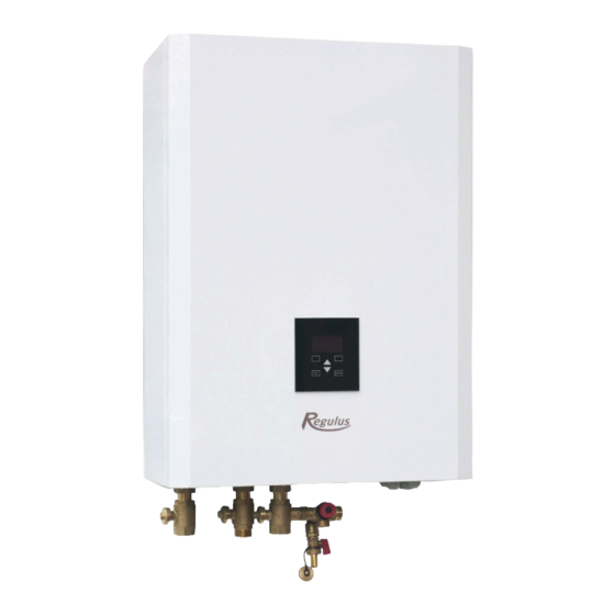
Page 6: A3. Description
Information on the current operating status can be read on the control unit with display located on the front cover of RegulusBOX. The connecting cable of the control unit is not connected (to avoid being unintentionally torn out during installation). It needs to be connected to its counterpart marked “Display”... -
Page 7: A4. Components
9 – Terminal block for connecting power supply, heat pump and other accessories 10 – Rear cable entry 11 – IR RegulusBOX controller with remote access from a computer or mobile app 12 – Safety thermostat 13 – Auxiliary internal terminal block 14 –... -
Page 8: A5. Parameters
A5. Parameters Technical Data Fluid working temperature 5-90 °C Max. working pressure 3 bar Min. working pressure 0.5 bar Ambient temperature 5-40 °C Max. relative humidity 80 %, non-condensing Safety valve set pressure 3 bar Safety valve seat cross section 132 mm Safety valve discharge coefficient 3-way valve actuator shift time... -
Page 9: Installation, Connection
B2. Installation Site Requirements ● RegulusBOX shall be installed indoors only. ● Ensure that no water can enter RegulusBOX at the installation site. ● Do not install the device in areas with a bath or shower in zones 0, 1 and 2. -
Page 10: B3. Wall Mounting
1 - outlet to heating system 2 - outlet to HW storage tank 3 - inlet from heat pump B. Install the enclosed fittings on the outlet pipe from RegulusBOX: 1 - G 1“ F ball valve on the outlet to the heating system 2 - G 1“... -
Page 11: B4.1 Hydraulic Variant With Hsk Thermal Store
B4.1 Hydraulic Variant with HSK Thermal Store │... -
Page 12: B4.2 Hydraulic Variant With Nbc Hot Water Storage Tank
B4.2 Hydraulic Variant with NBC Hot Water Storage Tank │... -
Page 13: B5. Electrical Wiring
B5. Electrical Wiring B5.1. Cable Entry Cables can be routed into RegulusBOX in two ways: via cable glands on the bottom of RegulusBOX or via a passage in the back plate of RegulusBOX. Note: The power supply cable is used not only to supply RegulusBOX, but also to supply the... -
Page 14: B5.2. Electric Wiring Of Regulusbox
B5.2. Electric Wiring of RegulusBOX Cable with Ripple control signal Power supply for RegulusBOX Outlet for heat pump power supply Universal relay Power supply for external (optional) pump PWM signal to an external (optional) pump CIB bus Communication with heat pump... -
Page 15: B5.3. Complete Inner Wiring Diagram
B5.3. Complete Inner Wiring Diagram │... -
Page 16: B5.4. Wiring Diagram Of M&R Peripherals To Regulusbox
B5.4. Wiring Diagram of M&R Peripherals to RegulusBOX │... -
Page 17: B5.5. Connection And Adjustment Of Optional Accessories - Room Sensor/Unit, Thermostat
B5.5. Connection and Adjustment of Optional Accessories - room sensor/unit, thermostat In each heating zone, it is possible to measure the room temperature using one of the following elements: - Pt1000 room sensor - RC25 room unit - RCD room unit - RCA room unit (buil-in display that is included in supply) - WiFi RSW 30 Wireless room sensor - current room thermostat with NO or NC contacts... -
Page 18: B5.6. Installation Of Optional Relay Sub-Module
B5.6. Installation of Optional Relay Sub-module The optional relay sub-module contains 4 relay outputs (250VAC/5A) marked DO24, DO25, DO26 and DO27. Push the relay sub-module gently into the controller board and fix it with the two screws included in supply. Controller board before the sub-module installation: Controller board after the sub-module installation: │... -
Page 19: B6. Pre-Commissioning Inspection
B6. Pre-commissioning Inspection Before commissioning the device, make sure that: • the heating system has been properly flushed and filled with clean and treated water • the installation site requirements specified in chapter B.2 of this manual have been respected •... -
Page 20: Settings Using The Main Display
C. SETTINGS USING THE MAIN DISPLAY A control panel designed for user system settings is located on the front cover. The panel consists of a display and six control buttons: ESC to return to the previous screen. ENTER to select and save a value Up and down arrows to scroll through menus or adjust values. -
Page 21: C1.1. Settings For Heating
C1.1. Settings for HEATING To access the HEATING menu from the home screen, press the SETTINGS button C1.2. Settings for HOT WATER You can access the HOT WATER menu from the home screen by pressing the SETTINGS button and then pressing the down arrow button once. │... -
Page 22: C1.3. Settings For Dhw Recirculation
C1.4. Other settings To access the menus for HEAT PUMP, ADDITIONAL SOURCE and REGULUS ROUTE from the home screen, press the SETUP button and then press the down arrow button three, four and five times. -
Page 23: How To Set Access To Controller Website
D. HOW TO SET ACCESS TO CONTROLLER WEBSITE The controller contains an integrated website showing an overview of the heating system and user settings. To reach web access to the controller‘s website it is necessary to connect the controller either to the local network or directly to the PC using a network cable. Alternatively, it is possible to use the IR Client mobile application. - Page 24 1. Click on Ethernet - a window with the connection status will open 2. Click on Properties at the bottom, the Ethernet properties window will open 3. Double-click on IP Protocol version 4 - a window with protocol properties will open. This window can also be accessed in other ways.
-
Page 25: D3. How To Connect Via Ir Client Mobile Application
Regulus IR Client is free to download from (for Android) and (for iOS). After logging in to the IR controller via the web interface using the Regulus IR Client application or the RegulusRoute service, the basic screen with tiles is displayed. │... -
Page 26: Setting The Controller Through Web Browser
When editing values (numbers, texts), it is necessary to confirm the change after each change by pressing the SAVE CHANGES button. Home page shown in the Regulus IR Client mobile application The drop-down menu to enter the individual sections for settings can be opened by clicking on the icon in the upper left corner;... -
Page 27: E2. Tiles For Heating And Hot Water
E2. Tiles for Heating and Hot Water When adjusting the temperature using the plus and minus buttons, the desired temperature is adj- usted depending on the current mode (T comfort, T setback). You will get to detailed zone The ON / OFF button is setting by clicking on this used to turn the zone on button. -
Page 28: E4. Display Of The Diagram (Diagram)
E4. Display of the Diagram (DIAGRAM) Schematic representation of your hydraulic connection with a clear display of important quantities, states and information. The diagram should therefore always correspond to your current hydraulic connection. For proper display in the mobile application, it is necessary to rotate the device for land- scape view. -
Page 29: E6. Heating Zone Settings (Zone 1 To 6)
E6. Heating Zone Settings (Zone 1 to 6) The heating zone can be switched on or off by the user with the ON/OFF button. If the zone is swit- ched off by the user, the circulation pump is switched off and the mixing valve is moved to the closed position. -
Page 30: E6.3. Summer/Winter Fuction Settings
E6.3. Setting the Winter/Summer function (blocking heating in the summer) When activating HEATING BLOCKED IN SET PERIOD, enter the date of beginning and end of the period when heating will be always blocked, disregarded of the current outdoor temperature. When activating HEATING BLOCKED BY OUTDOOR TEMPER., enter the time intervals for the set outdoor temperatures after which heating will be blocked (SUMMER mode permitted) and permitted (WINTER mode permitted). - Page 31 Object overheating at temperatures above zero If the building overheats at an outdoor temperature above zero, the heating water temperature must be reduced with the minus button. It can be seen from the graph that the heating water temperature is adjusted mainly at temperatures above the freezing point.
-
Page 32: E7. Aku Zone
Expert settings are intended for more experienced users, there are two pairs of plus and minus bu- ttons. One for temperatures above zero and the other for temperatures below the freezing point. By clicking on the individual buttons, the heating curve is reset mainly in the values corresponding to the location of the buttons according to the graphs above. -
Page 33: E10. Dhw Menu (Hot Water)
E10. DHW Menu (HOT WATER) DHW heating is divided into DHW-HP (DHW heating by heat pump), DHW-E (DHW heating by auxiliary source). If the hot water recirculation function is switched on, there is also a SET CIRCULATION tile. E10.1. Hot Water Heating by Heat Pump Hot water heating by heat pump can be switched on or off using the ON/OFF button. -
Page 34: E11. Hot Water Recirculation Settings
E11. Hot Water Recirculation Settings The DHW recirculation by auxiliary source can be switched on or off by the user with the ON/OFF button. Setting intervals Recirculation time - setting the running time of the circulation pump (pump running) Delay time - setting the delay time of the circulation pump (pump stopped) The time program settings are identical to the time program settings in zones 1 - 6. -
Page 35: E12.2. Solar Heating
E12.2. Solar Heating The solar circuit can be switched on or off by the user with the ON/OFF button (the safety recooling functions remain in operation when switched off). During commissioning, the service technician sets the right differential values for switching the solar system on and off. -
Page 36: E12.4. Regulusbox Electric Heating Elements
Information about faults or abnormal operation is sent automatically to the Regulus service department. If you want to send the information to other addresses as well, you can fill it in the E-mail Recipient line. Separate the addresses with a semicolon. -
Page 37: E13.5. Weather Forecast
E13.5. Weather Forecast The forecast can be switched on or off with the ON/OFF button. The weather forecast function is used to display the current weather and the forecast for the next day. Weather information is obtained from the yr.no server. After turning on the weather forecast, it is necessary to enter the state, region, and location on the settings page to refine the information. -
Page 38: E13.9. Universal Outputs
Summer bypass function The summer bypass function can be switched on or off with the ON/OFF button. In this section, the desired temperature and the relative heating zone are set (a room sensor must be located in this zone). If the room temperature in the heating zone is higher than the set limit and at the same time the conditions for the outdoor temperature (set at the service level) are met, the summer bypass opens. -
Page 39: Adjusting The Controller Through The Service Display
F. ADJUSTING THE CONTROLLER THROUGH THE SERVICE DISPLAY Warning: The service display is located in the electrical installation section of the device, where the live components are located. Therefore, the service display can only be operated by a service technician with electrical qualification. F1. -
Page 40: F2.2. Zone Display (Zone 1, Zone 2)
F2.2. Zone Display (zone 1, zone 2) 1 - zone status (information on the current status of the heating zone) 2 - actual and desired room temperature (if a room sensor is not used, the value is 0.0) 3 - correction of the desired room temperature; when a room unit is used, the „PJ“ symbol is displayed and the correction by this unit is displayed 4 - actual and desired heating water temperature to the zone The table below lists the possible operating states indicated on the service display and... -
Page 41: F2.3. Solar Thermal System Display
F2.3. Solar Thermal System Display 1 - solar collector temperature 2 - turn on the system 3 - ON = solar pump running 4 - mark of the currently heated hot water storage tank 5 – HW storage tank 1, actual temperature (desired in solar heating) 6 –... -
Page 42: F2.6. Display Of Heat Pump, Heat Pump Cascade (Hp In Series)
F2.6. Display of Heat Pump, Heat Pump Cascade (HP in series) 1 - status of heat pump No. 1, No. 2 and No. 3. This section shows the states of the heat pumps that are enabled on the service level. The states can be as follows: •... -
Page 43: F2.7. Display With Firmware Version And Release Date
F2.7. Display with Firmware Version and Release Date F2.8. Controller in Factory Settings If there is the screen shown on the display (see below) with a warning about setting the controller to factory settings, it is necessary that a service technician sets the relevant parameters of the controller. F2.9. -
Page 44: F3. User Settings
F3. User Settings Use the ◄ ► buttons to select between the options in the user settings; confirm the selection with the button; after completing all settings, press the × button to return to the first - basic display. F3.1. Heating Zones Basic settings of the heating zone T comfort (°C) setting the comfort temperature in the zone (desired room temperature) -
Page 45: F3.3. Time Programs
F3.3. Time Programs Setting the time program by days - set for each day of the week two transitions from setback mode to comfort mode and two transitions from comfort mode to setback mode. Setting the time program block by block - set the transitions similarly for the Mon-Fri and Sat-Sun block. -
Page 46: F3.8. Settings Of Dhw Heating By The Heat Pump (Dhw-Hp)
F3.8. Settings of DHW Heating by the Heat Pump (DHW-HP) DHW on user activation of DHW heating by the heat pump T comfort (°C) desired temperature in „comfort“ mode T setback (°C) desired temperature in „setback“ mode During the day, the controller switches the desired DHW temperature from the heat pump according to the set time program. F3.9. -
Page 47: F3.13. Operating Data
F3.16. RegulusRoute - Service Connection Parameters RegulusRoute service allows remote access to the controller without the need to use a public IP address. Pleaase contact Regulus to configure the service. RegulusRoute (yes/no) indicates whether the service is switched on Status... -
Page 48: F4.2. Uni Module, Uni Module 2
Temperature (°C) – displays the fireplace flow temperature. Damper (%) – displays how opened the fireplace air inlet damper is. DHW pump – displays the status of the pump for DHW heating from Thermal Store (running/off). F4.2. UNI Module, UNI Module 2 Output (on/off) - displays the status of the universal output at the UNI module (1, 2). -
Page 49: Maintenance
G. MAINTENANCE G1. Maintenance by the User It is recommended to perform this type of maintenance once a month: • Pressure check (locally or remotely via remote access). If necessary, air vent and top up water to the heating system. •... -
Page 50: G4. Removing The Wiring Cover
G4. Removing the Wiring Cover Warning: Danger of electric shock if live parts are touched! Before starting work, disconnect the RegulusBOX from the power supply (by switching off the relevant circuit breaker in the house switchboard). Disassembly of the wiring cover may only be carried out by a person professionally qualified in ac- cordance with EN 50110-1! The cover is attached with two screws at the bottom. -
Page 51: G6. Discontinuing Operation
If there is a risk of water freezing in the device (e.g. if the device is out of operation in an unheated room), drain all water from the RegulusBOX, the heat pump and the pipes - especially in places where the temperature may drop below 0 °C. And also turn off the RegulusBOX circuit breaker in the home fusebox. -
Page 52: H2. Record Of Repairs And Inspections
H.2. Record of Repairs and Inspections Service company Customer‘s Date Operation performed Name, signature and stamp signature │... - Page 53 Service company Customer‘s Date Operation performed Name, signature and stamp signature │...
- Page 54 │...
-
Page 55: Declaration Of Conformity
- value 1 or 3 indication of communication with the heat pump CTC or RTC, or not used at all (communication has no influence on the function of RegulusBOX) heating elements output in kW - value of 3, 6, 9, 12 type This Declaration of Conformity is issued under the sole responsibility of the manufacturer. - Page 56 ©2021 We reserve the right to errors, changes and improvements without prior notice. REGULUS spol. s r.o. E-mail: sales@regulus.eu Web: www.regulus.eu...
Need help?
Do you have a question about the RegulusBOX and is the answer not in the manual?
Questions and answers