Table of Contents
Advertisement
Quick Links
Installation and Operation Data
Installation and
Op er a tion Man u al
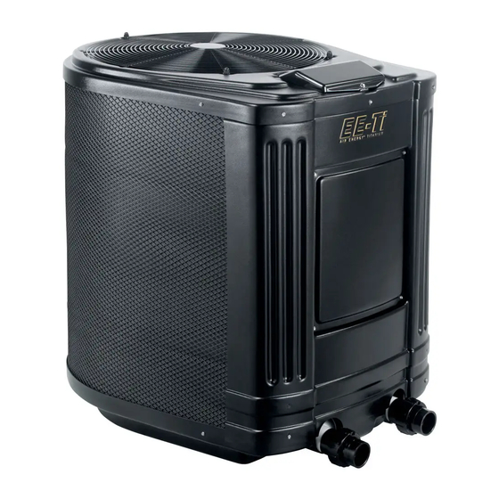
Air Energy
Heat Pumps
Model AE-Ti
RISK OF ELECTRICAL SHOCK OR ELECTROCUTION. The electrical supply to this product
must be installed by a licensed or certifi ed electrician in accordance with applicable national and
local codes and ordinances. Improper installation will create an electrical hazard, which could
result in death or serious injury to pool or spa users, installers, or others due to electrical shock,
and may also cause damage to property. Read and follow the specifi c instructions inside this
manual.
™
DANGER
Advertisement
Table of Contents
Troubleshooting

Subscribe to Our Youtube Channel
Related Manuals for Jandy Air Energy AE-Ti


Summary of Contents for Jandy Air Energy AE-Ti
- Page 1 Installation and Operation Data Installation and Op er a tion Man u al Air Energy ™ Heat Pumps Model AE-Ti DANGER RISK OF ELECTRICAL SHOCK OR ELECTROCUTION. The electrical supply to this product must be installed by a licensed or certifi ed electrician in accordance with applicable national and local codes and ordinances.
-
Page 3: Table Of Contents
Page 1 Table of Contents Section 1. General Information ....5 4.5.2 Two-Wire Connection to an AquaLink ® or TSTAT ............ 21 Introduction ............5 4.5.2.1 Configure the AquaLink RS Control ® Consumer Information and Safety ...... 5 System ..........21 1.2.1 Spa/Hot Tub Safety Rules ...... - Page 4 Page 2 Table of Contents (Continued) 7.3.6 Load Defaults ..........31 7.3.7 Coil Temperature Calibration ..... 31 7.3.8 Water Temperature Calibration ....31 7.3.9 Water Temperature Differential ....31 7.3.10 Delay On Make .......... 32 7.3.11 Last Fault ........... 32 Section 8.
-
Page 7: Section 1. General Information
Page 5 Section 1. General Information Consumer Information and Safety The AE-Ti series of heat pumps are designed and manufactured to provide many years of safe Introduction and reliable service when installed, operated and maintained according to the information in this manual This manual provides installation and operation and the installation codes referred to in later sections. -
Page 8: Swimming Pool Energy Saving Tips
Page 6 Persons taking any medication which induces Find the proper setting on the heat pump drowsiness (e.g., tranquilizers, antihistamines, or temperature control and use the Set Point Lockout anticoagulants) should not use spas or hot tubs. function or lock the cover on the heat pump controller to discourage further adjustments. -
Page 9: Technical Assistance
Page 7 All Air Energy™ heat pumps must be installed in 1.6.2 Recommended Materials for accordance with the local building and installation Installations codes as per the utility or authority having Air Energy™ recommends installing isolation jurisdiction. All local codes take precedence over valves on the inlet and outlet water connections for ease national codes. -
Page 10: Technical Specifications
Page 8 Figure 1. AE-Ti Heat Pump Dimensions DIMENSIONS MODEL SIZE “A” “B” “C” “D” “E” “F” “G” 66 cm 79 cm 18,5 cm 62 cm 55 cm 33 cm 89 cm 66 cm 79 cm 18,5 cm 62 cm 55 cm 33 cm 89 cm... -
Page 11: Section 2. Installation Instructions
Page 9 Section 2. Installation Instructions Avoid placing the heat pump in locations where it can cause damage by water or condensate leakage. If this is not possible, provide a suitable drain pan to catch and divert any leakage. All criteria given in the following General Information sections reflect minimum clearances. -
Page 12: Indoor Installations
Page 10 2.2.4 Indoor Installations 2.2.5 Outdoor Installations See Figure 2 (Standard Plumbing Layout). CAUTION When pool equipment is located below the pool NOTE Indoor installations require special considerations surface, a leak from any component can cause for condensate drainage and venting the cold air large scale water loss or fl... -
Page 13: 2.2.5.2 Roof Run-Off
Page 11 Filtered water is plumbed to the inlet, located on 2.2.5.2 Roof Run-off the right side of the heat pump front panel. Heated water Make sure the heat pump is not located where flows through the outlet, located on the left side of the large amounts of water may run off from a roof into heat pump front. -
Page 14: Figure 3. Shared Filtration System
Page 12 Shared Filtration Systems Heat Pump to Heat Pool Heat Pump to Heat Spa Pool Pool 3-way valve Filtration Pump Filter Figure 3. Shared Filtration System Independent Filtration Systems Heat Pump to Heat Pool Heat Pump to Heat Spa Pool Pool 3-way valve... -
Page 15: Multiple Unit Installation
Page 13 Heater Heat Pump Pool Return Check Valve From Solar Make-Up Check Valve Pool Intake To Solar Filter Spa Return Pool Drain Pump Filter Spa Intake Spa Drain Figure 5. Plumbing For Heating System Combinations Multiple Unit Installation NOTE It may be necessary to adjust water pressure switch if a unit is installed below the water level. -
Page 16: Figure 6. Two Heat Pump Plumbing Layout
Page 14 30 cm minimum clearence around evaporator 30 cm NOTE! Gate Valves are optional on heater inlets but will help for system balancing 50 mm 50 mm Extend 30 cm past end heater inlet for Extend 30 cm hydraulic past end balancing heater inlet... -
Page 17: Figure 8. Six Heat Pump Plumbing Layout
Page 15 30 cm minimum clearence around evaporator evaporador 30 cm NOTE! Gate Valves are optional on heater inlets but will help for system balancing 50 mm 50 mm 50 mm 50 mm 50 mm 50 mm 90 mm pvc pipe Extend 41-51 cm past end heater inlet for Extend 41-51 cm past... -
Page 18: General Information
Page 16 General Information CAUTION Wiring connections must be made exactly as This heater must be connected to a bonding grid shown in the wiring diagram found on the inside of with a solid copper wire not smaller in diameter the heat pump access compartment. -
Page 19: Figure 10. Ae-Ti Single-Phase Electrical Supply Wiring Diagram
Page 17 TO FILTRATION PUMP ELECTRICAL BOARD (SEE FIGURE 13) Figure 10. AE-Ti Single-Phase Electrical Supply Wiring Diagram... -
Page 20: Figure 11. Ae-Ti 3-Phase Electrical Supply Wiring Diagram
Page 18 AHin TO FILTRATION PUMP ELECTRICAL BOARD (SEE FIGURE 13) AHout BK BK BK BK Y-OUT THREE PHASE LINE VOLTAGE AE SERIES MONITOR 380 - 420 VAC GR Y BK R (3~)THREE PHASE 50Hz WIRING DIAGRAM 380/420~ 380/420~ BR/W INTAKE RETURN SEE INSTALLATION AND OPERATION... -
Page 21: Figure 12. Electrical Wiring Diagram Symbol
Page 19 SYMBOL DEFINITIONS PUMP PUMP TIME CLOCK COMPRESSOR WATER TEMPERATURE SENSOR AIR TEMPERATURE SENSOR FAN CAPACITOR COMPRESSOR CAPACITOR WATER PRESSURE SWITCH HIGH REFRIGERANT PRESSURE LIMIT SWITCH LOW REFRIGERANT PRESSURE LIMIT SWITCH POOL FACTORY INSTALLED 208/230 VAC 208/230~ FACTORY INSTALLED 380/420 VAC 380/420~ FIELD INSTALLED 208/230 VAC 208/230~... -
Page 22: Figure 13. Example Of Wiring To The Time Clock For Enabling The "Maintain Temp" Feature
Page 20 On/Off Breaker Contactor Filter Pump Power Timer AHin AHout To Heat Pump (See Figure 10 and 11) Figure 13. Example of wiring to the Time Clock for enabling the “MAINTAIN TEMP” feature MAINTAIN TEMP TO TIME CLOCK CONNECTION SERVICE ACCESS PANEL (4 SCREWS) CONNECTOR FOR HIGH... -
Page 23: Configure The Control Panel
Page 21 4.5.1.2 Confi gure the Control Panel 4.5.2.2 Install the Remote TSTAT or AquaLink ® Make sure the control is in the OFF mode. Turn off the power to both the pool/spa control To enter the Service Setup mode, press and hold system and the heat pump unit. -
Page 24: Four-Wire Connections To Aqualink
RS control connected to the heat pump, the Remove the two screws holding the bezel in place display on the heat pump will show "JANDY REMOTE and turn the bezel over to view the circuit board on ONLINE PUSH MENU TO DISABLE"... -
Page 25: Connection To A Secondary User Interface
MENU button for 5 seconds to enter the on the lower right hand side of the heat pump. See User Setup Mode and then enable the Jandy Remote. Figure 14. The wires may be up to 300 feet in length. -
Page 26: Operating The Controller
Page 24 Clean the filter at the end of this operation before The associated left green LED indicator will starting the heat pump. When raising the temperature light and the unit will display SET:XXX°. Change the of a cold pool, program the time clock to run the pump temperature set point by pressing the Up or Down continuously. -
Page 27: Operating Features Of Units With Optional Chiller
Page 25 When the water temperature drops below the To operate in pool mode with the Maintain Chill programmed temperature set point, the control will start feature, press POOL , then press MENU , then press the heat pump. the Down button until MAINTAIN POOL CHILL is displayed, press the MENU button. -
Page 28: Temperature Scale Setup
Page 26 5.4.2 Temperature Scale Setup to select. Use the Up or Down button to scroll to display SELECT DISPLAY LIGHT LIGHT Make sure the control is in the OFF mode. OFF , this option allows the display light to turn off, press the MENU button to select. -
Page 29: Section 6. General Maintenance
Page 27 On some installations, the piping from the heat If the water pressure switch cannot be adjusted pump to the pool is very short. The back pressure to accommodate the conditions listed above, could be too low to trigger the pressure switch. If this an external fl... -
Page 30: Spring Start-Up
Page 28 Spring Start-Up The heat pump will produce condensation (water) while in operation. The heat pump base is designed to If your heat pump has been winterized, perform the allow the condensation to exit through the bottom drain following steps when starting the system in the Spring: port when the unit is running. -
Page 31: Professional Inspection
Page 29 Water Inlet Union Water Outlet Union Petcock (Leave open until unit is ready to start-up) Figure 19. Winterizing the AE-Ti Heat Pump 6.4.2 Professional Inspection When the fan is turned on, warm air is drawn through the refrigerant charged evaporator, turning Inspections performed at least once a year by a the cold liquid refrigerant to a warm gas. -
Page 32: Heat Pump Components And Their Operation
Page 30 The maintain temperature delay is used when Heat Pump Components and Their MAINTAIN TEMP is connected. This feature Operation allows for a time delay before the pump is turned Evaporator - As air passes through the on. To select Maintain Temperature Delay, use the evaporator, the refrigerant in the evaporator absorbs Up or Down button to scroll through to display heat from the ambient air. -
Page 33: Load Defaults
Page 31 7.3.8 Water Temperature Calibration CAUTION Make sure the control is in the OFF mode. Disable TEST MODE after use. Failure to disable TEST MODE after use will allow the To enter the Service Setup mode, press and hold heat pump to bypass the built-in delays, which the MENU, POOL and SPA button for 5 seconds. -
Page 34: Delay On Make
Page 32 7.3.10 Delay On Make Make sure the control is in the OFF mode. To enter the Service Setup mode, press and hold the MENU, POOL and SPA button for 5 seconds. NOTE The display will revert back to OFF after one minute since the last key press. -
Page 35: Section 8. Troubleshooting
Page 33 Section 8. Troubleshooting Troubleshooting Guide The following table provides symptoms and solutions for general troubleshooting problems for the heat pump. SYMPTOM CORRECTIVE ACTION Heat pump will not start, no control board display. Breaker or fuse may be tripped. Reset breaker or check fuse. -
Page 36: Diagnostics
Page 34 Diagnostics In the event a pressure switch opens or another Please refer to the following table for the list of fault condition occurs, the LCD screen will display the diagnostic conditions. fault until the problem has been resolved. DIAGNOSTIC CONDITION DESCRIPTION FAULT-... -
Page 37: Resistance - Temperature, 10,000 Ohm "J
Page 35 TEMP. (°C) RESIS. (Ω) TEMP. (°C) RESIS. (Ω) TEMP. (°C) RESIS. (Ω) TEMP. (°C) RESIS. (Ω) 38,115 19,899 10,922 6,268 36,187 18,970 10,450 6,016 34,368 18,089 10,000 5,775 32,650 17,254 9,572 5,546 31,029 16,462 9,165 5,326 29,498 15,711 8,777 5,117 28,051... -
Page 38: Section 9. Replacement Parts
To order or purchase parts for the AE-Ti models of heat pumps, contact your nearest Air Energy™ dealer or distributor. If they cannot supply you with what you need, contact Jandy International Service Department located at: 2735 NW 63 Court, Fort Lauderdale, Florida, 33309 - USA, Tel: 1-954-970-4800. -
Page 39: Air Energy ™ Ae-Ti Heat Pump Exploded View
Page 37 Air Energy AE-Ti Heat Pump Exploded View ™ These pressure switches are installed in the refrigerant line near the compressor DETAIL “A” DETAIL “B” Figure 21. Air Energy™ AE-Ti Heat Pump Exploded View... - Page 40 ARE NOT FULFILLED. Model Serial Number Date Purchased Initial Start Up Dealer Name Installer Name Air Energy™ Heat Pumps 2735 NW 63 Court, Fort Lauderdale, Florida 33309, USA • 954.970.4800 FAX 954.971.8440 Litho in U.S.A. © 2007 Jandy Pool Products, Inc. 0703...
Need help?
Do you have a question about the Air Energy AE-Ti and is the answer not in the manual?
Questions and answers