Table of Contents
Advertisement
Installation and Operation Data
Installation and
Op er a tion Man u al
®
Jandy
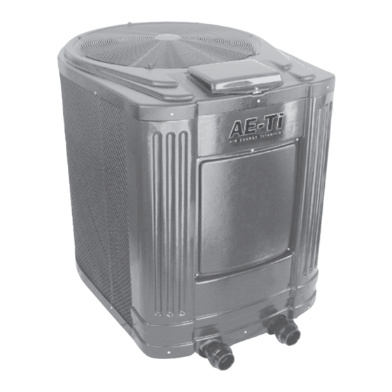
Heat Pumps
Model AE-Ti
RISK OF ELECTRICAL SHOCK OR ELECTROCUTION. The electrical supply to this product
must be installed by a licensed or certifi ed electrician in accordance with the National Electrical
Code and applicable local codes and ordinances. Improper installation will create an electrical
hazard, which could result in death or serious injury to pool or spa users, installers, or others
due to electrical shock, and may also cause damage to property. Read and follow the specifi c
instructions inside this manual.
RISQUE DE CHOC ÉLECTRIQUE OU ELECTROCUTION. Cet appareil doit être installé par un
électricien certifi é conformément au National Electrical Code et aux normes et règlementations
locales. Une installation incorrecte peut entraîner un risque de problème électrique ( choc
électrique ou électrocution) pouvant causer des blessures graves et même la mort des
installateurs et/ou utilisateurs de SPA et Piscines. Lire le manuel et se conformer aux directives.
RIESGO DE DESCARGA ELÉCTRICA O ELECTROCUTAMIENTO. El suministro eléctrico de
este producto deberá ser instalado por un electricista autorizado o diplomado, de acuerdo al
Código Eléctrico Nacional y a los códigos y normativas que apliquen localmente. Una instalación
inadecuada podría originar riesgos eléctricos y ocasionar la muerte o lesiones graves a los
usuarios de de la piscina o spa, instaladores u otros, como consecuencia de una descarga
eléctrica, pudiendo así mismo ocasionar daños a la propiedad. Léa y siga las instrucciones
específi cas que se recogen en este manual.
DANGER
DANGER
PELIGRO
Advertisement
Table of Contents

Subscribe to Our Youtube Channel
Related Manuals for Jandy AE-Ti


Summary of Contents for Jandy AE-Ti
- Page 1 Op er a tion Man u al ® Jandy Heat Pumps Model AE-Ti DANGER RISK OF ELECTRICAL SHOCK OR ELECTROCUTION. The electrical supply to this product must be installed by a licensed or certifi ed electrician in accordance with the National Electrical Code and applicable local codes and ordinances.
-
Page 3: Table Of Contents
Section 9. Replacement Parts....29 Optional Remote Controls ......16 Ordering Information ......... 29 4.5.1 Connection to an AquaLink RS Jandy® AE-Ti Heat Pumps Parts List..29 Control System ........16 Jandy® AE-Ti Heat Pumps Exploded View........... 30 Section 5. Operation .........18 Initial Start-up Precautions ...... -
Page 4: Section 1. General Information
Spa/Hot Tub Safety Rules Introduction This manual provides installation and operation WARNING instructions for the Jandy AE-Ti models of Heat Pumps. The U.S. Consumer Product Safety Commission Read these installation and operation instructions warns that elevated water temperature can completely before proceeding with the installation. -
Page 5: Swimming Pool Energy Saving Tips
Physical inability to leave spa Warranty • Fetal damage in pregnant women The AE-Ti heat pump is sold with a limited factory warranty. Details are specified on the back cover of this • Unconsciousness resulting in a danger of manual. -
Page 6: Codes And Standards
Jandy recommends installing isolation valves Codes and Standards on the inlet and outlet water connections for ease of The AE-Ti heat pump is listed by ETL as serviceability. complying with the latest edition of the “UL Standard for Safety for Heating and Cooling Equipment”, UL Specifi... -
Page 7: Dimensions
NOTE Indoor installations require special considerations for condensate drainage and venting the cold air produced by the heat Section 2. Installation Instructions pump. Contact the Jandy Heat Pump Technical Service Department at (954) 970-4800. General Information CAUTION Install the Jandy heat pumps in accordance... -
Page 8: Clearances
5 feet clearance from the top of the heat 5/8” diameter barbed adapter, Jandy p/n R3004100 (see pump. Section 9, “Replacement Parts”. If using the barbed This heat pump must be installed at least 5 feet adapter, connect a length of 5/8”... -
Page 9: Installation Of Anchor Clamps
Figure 3. Anchor Clamp Installation NOTE Bolts and bolt anchors are not included with the heat pump. Jandy recommends that a Drill a hole in the cement using a masonry drill 3/16” x 1¾” long stainless steel Tapcon ®... -
Page 10: Water Connections At Heat Pump
PRECAUCIÓN the heat pump. Call the Jandy Heat Pump Technical Asegúrese de que los requerimientos de fl ujo Service department at (954) 970-4800 for details. -
Page 11: Automatic Flow Control Valve
“Chiller” mode during the hottest portion of the year and a heater during the cooler months. The Jandy heat pump may be plumbed with a gas or electric heater or any combination of heat sources including solar. - Page 12 Page 10 12 inches min. clearence around evap. 12" NOTE! Gate Valves are optional on heater inlets but will help system balancing 2" pvc 2" pvc Extend 12" past Extend 12" past end heater inlet end heater inlet for hydraulic for hydraulic balancing balancing...
- Page 13 Page 11 12 inches min. clearance around evap. 12" NOTE! GATE VALVES ARE REQUIRED ON HEATER INLETS TO HELP SYSTEM BALANCING 2" pvc 2" pvc 2" pvc 2" pvc 2" pvc 2" pvc FLOW METER FLOW METER FLOW METER FLOW METER FLOW METER FLOW METER 4"PVC PIPE...
-
Page 14: Section 4. Electrical Connections
Page 12 General Information Section 4. Electrical Connections Wiring connections must be made exactly as shown in the wiring diagram found on the inside of the WARNING heat pump access panel (see Figure 10 for single phase ELECTRICAL SHOCK HAZARD. This heat electrical wiring and Figure 11 for 3-phase electrical pump contains wiring that carries high voltage. - Page 15 Remote BR/W - WHITE W/BR - WHITE WITH BROWN TRACE W/GY - WHITE WITH DigitalControl GRAY TRACE - WHITE WITH RED TRACE - WHITE WITH FAN MOTOR VIOLET TRACE - YELLOW H3000200A Figure 10. AE-Ti Single-Phase Electrical Supply Wiring Diagram...
-
Page 16: Wiring Diagram
Remote - WHITE BR/W W/BR - WHITE WITH BROWN TRACE W/GY - WHITE WITH DigitalControl GRAY TRACE - WHITE WITH RED TRACE - WHITE WITH VIOLET TRACE FAN MOTOR - YELLOW H3000300A Figure 11. AE-Ti 3-Phase Electrical Supply Wiring Diagram... -
Page 17: Main Power
All wiring must be done by diameter than 8 ga. a certified electrician. The following is the procedure to wire the AE-Ti ATTENTION to the electrical source specified on the Rating Plate: L’appareil de chauffage doit être connecté à... -
Page 18: Pump Connection (Auto-Heat Feature)
(see Figure 12 on page 15). This will allow you to access the wires from the AE-Ti control panel for the remote control installation (see Figure 13). Figure 13. AE-Ti Control Panel, Interior View Run the wires from the pool/spa control system into the conduit connection labeled “Low Voltage... - Page 19 Heat Pump Voltage Wires Service/Wiring Cover Panel Figure 15. AquaLink RS to AE-Ti Heat Pump/Chiller Wiring NOTE One end of the wiring reserved to run into the conduit connection labeled “Low Voltage Connection”, located on the lower right hand side of the heat pump (see Figures 12 and 14).
-
Page 20: Section 5. Operation
Operating the Controller PRECAUCIÓN Your new AE-Ti heat pump is controlled by an No utilice esta bomba de calor si algunos de advanced microprocessor based controller that provides sus componentes han estado debajo del agua. a sophisticated yet simple interface to operate your heat Póngase inmediatamente en contacto con un... -
Page 21: Pool Mode (Optional Auto Heat)
Page 19 Figure 16. Main Control Panel 5.2.3 Pool Mode - (Optional Auto Heat) 5.2.5 Keypad Lockout If connected, the Auto-Heat mode allows the in any operating mode To lockout the keypad heat pump to monitor the temperature of the water 24 press and hold the POOL , SPA , and Heat/Cool buttons hours a day by turning the pool pump on and sampling for 6 seconds. -
Page 22: Operating Features Of Units With Optional Chiller
Page 20 desired set point. After 5 seconds of inactivity the Operating Features of Units with display will read SPA AUTO-HEAT along with the Optional Chiller current spa temperature and the delay time left until the chiller starts. Additionally, the new set point will be 5.3.1 Pool Mode - (Normal Cool) stored in memory. -
Page 23: Advanced Digital Microprocessor Quick Guide
15 feet (4.57 m) above or 6 feet Reverse Cycle equipped heat pumps. Press Heat/ (1.83 m) below the pool surface. Consult your local Cool to reverse roles from heating to cooling the Jandy representative for recommendations. pool to the desired temperature. -
Page 24: Section 6. General Maintenance
Page 22 Check the setting of the water pressure switch by On some installations, the piping from the heat pump to the pool is very short. The back pressure starting and stopping the fi lter pump and checking could be too low to trigger the pressure switch. If this the control display and operation of the heater happens, it may be necessary to install a directional between each fl... -
Page 25: Spring Start-Up
Petcock (Leave open until unit is ready to start-up) Figure 17. Winterizing the AE-Ti Heat Pump Open the drain located on the lower front panel of Turn on the fi lter pump to supply water to the the heat pump to drain the remaining water from heat pump. -
Page 26: 6.4.2 Professional Inspection
Page 24 Keep all plants and shrubs trimmed and away from 6.4.2 Professional Inspection the heat pump. Inspections performed at least once a year by a qualified technician are required to maintain your heat Do not use this heat pump if any part has been pump’s safe and efficient operation. -
Page 27: Section 7. Professional Maintenance And Service
Section 7. Professional Maintenance and Service Heat Pump Design The Jandy Air Energy Heat Pump is one of the most efficient ways to heat a pool or spa. The heat pump transfers heat from the outside air to the pool or spa water by means of an internal heat exchanger. -
Page 28: Section 8. Troubleshooting
Page 26 Section 8. Troubleshooting Troubleshooting Guide SYMPTOM CORRECTIVE ACTION Heat pump will not start, no control board display. Breaker or fuse may be tripped. Reset breaker or check fuse. If heat pump still does not run, call for service. Heat pump will not start, control board display working. -
Page 29: Diagnostics
Page 27 Diagnostics In the event a pressure switch opens or another the fault until the problem has been resolved. Please fault condition occurs, the LCD screen will display refer to the following table for the list of diagnostic conditions. Diagnostic Condition Description LOW H 2 O FLOW... - Page 30 Page 28 Diagnostic Condition Description LOW WATER TEMPERATURE When the POOL or SPA temperature chills to 50°F or below there could be safety risks for anyone in the water. The water sensor will read this temperature and the control will shut off the chiller.
-
Page 31: Section 9. Replacement Parts
Section 9. Replacement Parts Ordering Information for the nearest service center. If they cannot supply you To order or purchase parts for the AE-Ti models with what you need, contact Jandy Customer Service of heat pumps, contact your nearest Jandy dealer or Department at P.O. -
Page 32: Jandy Ae-Ti Heat Pumps Exploded View
Page 30 Jandy AE-Ti Heat Pumps Exploded View 24, 26 This 10K thermistor is used as a water temperature sensor when installed in the water inlet pipe and as an air temperature sensor when installed in the evaporator coil. Please note that the water temperature sensor wiring is blue and the air temperature sensor wiring is red. - Page 33 Page 31 Notes...
- Page 34 Page 32 Notes...
- Page 35 Page 33...
-
Page 36: Limited Warranty
If the dealer is not available, you can locate a service center in your area by visiting www.jandy.com or by calling our technical support department at (707) 776-8200 extension 260 [for heap pumps call (954) 970-4800]. All returned parts must have a Returned Material Authorization number to be evaluated under the terms of this warranty.
Need help?
Do you have a question about the AE-Ti and is the answer not in the manual?
Questions and answers