Table of Contents
Advertisement
Quick Links
Advertisement
Table of Contents

Related Manuals for Cattron Messenger BLE


Summary of Contents for Cattron Messenger BLE
- Page 1 Messenger BLE User’s Guide Version 1.0.38 September 30, 2020...
- Page 2 MessengerBLE User Guide...
-
Page 3: Table Of Contents
MessengerBLE User Guide Table of Contents Description ..........................7 Capabilities..................... 7 Monitoring ..................... 7 Host Server Communications................. 7 Installation and Setup ......................11 Installation Steps ..................11 Unpacking the Equipment ................11 Mounting the Equipment ................11 Mounting the Antenna.................. 12 DIP Switch/Jumper Settings ................ - Page 4 MessengerBLE User Guide 9.18 EVAL Expression Configuration – Type 10 ..........72 9.19 J1939 PGN Configuration – Type 15 ............75 9.20 J1939 SPN Configuration – Type 14 ............76 9.21 PEER Poll Configuration – Type 28 ............78 9.22 PEER Push Configuration –...
- Page 5 Use of the materials by the Government constitutes acknowledgment of Cattron’s proprietary rights in them. This manual may contain other proprietary notices and copyright information that should be observed.
- Page 6 MessengerBLE User Guide Introduction This User’s Manual describes installation and setup of the Messenger-BLE product. Throughout this document, Messenger-BLE and Messenger are used interchangeably. The Messenger is a complete monitoring, alarm notification, and telemetry platform. The intended markets include (but not limited to) water/wastewater utility, off-road heavy construction equipment, on-road semi-trucks, oil and gas, and standby power generators.
-
Page 7: Description
MessengerBLE User Guide 1 Description 1.1 Capabilities The Messenger is a highly configurable platform for remote monitoring and control applications. Some of the capabilities are listed below. virtual real-time transfer of monitored conditions local computations from monitored conditions ... - Page 8 MessengerBLE User Guide date/time, an event code, and associated data. An event code provides a unique identifier to indicate the reason that notification is being sent – e.g. normal scheduled update or an engine diagnostic message received. A description of the protocol, format of messages, and definition of event codes is available on request (reference protocol document “M09-PRTCLxxx”).
- Page 9 MessengerBLE User Guide acknowledged. This store and forward memory is non-volatile and remains intact during power off. 1.3.4 Real-Time Clock (RTC) The RTC is used to timestamp data records and events. All messages sent to the host server contain a timestamp to provide a chronology of data/events to the end user. This timestamp is UTC time.
- Page 10 MessengerBLE User Guide 1.3.6 Specifications Power input: 8-36 vdc 26 mA @ 24vdc (avg) reverse polarity protection overvoltage protection internal solid-state fuse Digital outputs (3 ea): Open-collector transistor switch to ground (current sink) 500mA @ 12vdc current limited overvoltage protection Digital inputs (4 ea): two modes of operation, DC voltage input or grounded input (user selectable) high-speed pulse counter inputs (user selectable)
-
Page 11: Installation And Setup
MessengerBLE User Guide 2 Installation and Setup This section provides information on installing the Messenger and confirming its initial operation. WARNING It is recommended to read this entire chapter before starting installation. 2.1 Installation Steps Installation consists of the following steps: Unpack the Equipment. -
Page 12: Mounting The Antenna
MessengerBLE User Guide Mount the enclosure in a vertical orientation and provide service loops for each antenna and IO cable to prevent water intrusion. 2.3.1 EEC Thermoplastic Enclosure Figure 1: Deutsch EEC Thermoplastic Enclosure Dimensions When mounting the enclosure to vibrating equipment, it is recommended to use rubber dampeners to isolate the unit. -
Page 13: Dip Switch/Jumper Settings
MessengerBLE User Guide CAUTION Service loops should be provided for the antenna cabling, near the antenna connections to minimize water ingress through the SMA RF coax connections. 2.5 DIP Switch/Jumper Settings The Messenger uses an on-board DIP switch and jumpers to configure application specific IO and set operational modes. -
Page 14: Dip Switch 3 Decode
MessengerBLE User Guide 2.6 DIP Switch 3 Decode DIP Switch 3 is a 4-position dip switch located on the left side of the board (Figure 3). If any switch 3 position is changed, the power must be cycled for the new switch positions to be read. -
Page 15: Io Connections
MessengerBLE User Guide 2.7 IO Connections The Deutsch EEC enclosure has a water tight end-cap fitted with one M12x8 MALE connector (JR2-PRI), one M12x8 FEMALE connector (JR1-SEC), one SMA JACK GPS antenna connector, and one SMA-RP JACK CELL antenna connector. See figure x. Figure 3: Messenger IO Connectors Depending on the customer input/output requirements, there may be 1 or 2 cable harnesses supplied for the customer to connect to his field signals. - Page 16 MessengerBLE User Guide Figure X: Messenger IO Signals MessengerBLE V+ (8-36vdc) IO Harness JR2 (Pri) Flying Lead PWR IN CAN L CAN H P1-RS485B DIN 1 AIN 1 CAN-L P1-RS485A Cables CAN-H 8-Pin Female M12 PVC Jacket P1-RS485A PVC Conductor Insulation JR1 (Sec) 8x22 P1-RS485B...
- Page 17 MessengerBLE User Guide Figure 4: User IO Jumper Location If digital outputs (DOUT1, DOUT2, or DOUT3) are to be used in the application...
-
Page 18: Cellular Setup
MessengerBLE User Guide 2.8 Cellular Setup The Messenger supports two cellular technologies, HSPA (3G) and LTE (4G). The current offering for HSPA is a 3G penta-band capable radio. For LTE, it is a 4G, dual- band radio. Both of these radio options require a wireless account with a cellular provider such as AT&T or Verizon. -
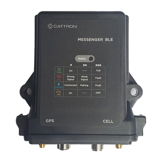
Page 19: Led States
MessengerBLE User Guide 3 LED States There is one tri-color LED visible to the user to indicate various system conditions. These conditions are conveyed to the user via LED color and blink patterns. Blinking of LEDs can be disabled via a configuration setting (OPTIONS Configuration). -
Page 20: Io Architecture
MessengerBLE User Guide 4 IO Architecture The IO architecture is shown in the diagram below. Each of the physical IO entities has a configuration that is set based on user requirements. Based on that configuration, the values sampled are stored in their respective data registers. These data registers are used to reference the corresponding value for use in channel creation or in expressions used to compute values. -
Page 21: Channels
MessengerBLE User Guide 5 Channels The Messenger maps all monitored conditions into channels. Each channel has data storage and configuration parameters. Data storage holds current value, max/min values, and other run time data values. Configuration consists of user settable parameters that define rules on how the data values are to be processed (Channel Configuration). - Page 22 MessengerBLE User Guide Channel Channel Type Source Data Description Number Name Register 0=normal User DIN1 Digital If SWX4-1 closed: 0=open 1=ground applied If SWX4-1 open: 1=open 0=voltage applied User DIN2 Digital If SWX4-2 closed: 0=input open ...
- Page 23 MessengerBLE User Guide Channel Channel Type Source Data Description Number Name Register 0=normal User DOUT1 Digital state of digital output 1 0=not energized 1=energized User DOUT2 Digital state of digital output 2 0=not energized 1=energized 32-39 Spare Digital...
- Page 24 MessengerBLE User Guide Channel Channel Type Source Data Description Number Name Register Eng RPM Analog Engine speed, RPM Eng HRS Analog Accumulated engine run time (hours) Coolant Analog degrees C Temp Battery Analog volts reading Electrical Analog volts reading Oil Pressure Analog Oil pressure in psi Fuel Rate...
- Page 25 MessengerBLE User Guide Channel Channel Type Source Data Description Number Name Register Oil Temp Analog degrees F Coolant Level Analog percent Throttle Analog percent Position Road Speed Analog Barometric Analog ambient pressure in psi Pressure Cabin Analog degrees F Temperature Ambient Analog degrees F...
- Page 26 MessengerBLE User Guide Channel Channel Type Source Data Description Number Name Register Accumulated flow volume Running Derived since last volume reset (flow Flow Volume rate from ADC input) Generator, Analog in kWH Total kW Hours Export Channels specific to Generators are available on Request Only Generator, Analog...
- Page 27 MessengerBLE User Guide Channel Channel Type Source Data Description Number Name Register AT1 DPF Support for tier 4 diesel Regen Analog engines Threshold DPF2 Soot Support for tier 4 diesel Analog Load engines DPF2 Ash Support for tier 4 diesel Analog Load engines...
- Page 28 MessengerBLE User Guide Channel Channel Type Source Data Description Number Name Register 290- Spare Start User-Defined Channels 301- User-Defined User Analog or Digital channels Defined...
-
Page 29: Channel Data
MessengerBLE User Guide 5.2 Channel Data All values read from physical IO, an engine bus, or from a Modbus slave device are continually updated and tested as defined by the configuration parameters. For each channel, based on its type (analog or digital), there is a basic set of data collected. For purposes of discussion, the term “not normal”... - Page 30 MessengerBLE User Guide The daily data set is a separate set of current and max/min values that span the 24 hour period from midnight to midnight, UTC time. At midnight, an end of day report is generated from this data. Because Modbus channel data is polled, Modbus digital channels do not maintain count or duration values.
-
Page 31: Sms Text Commands
MessengerBLE User Guide 6 SMS Text Commands The Messenger can receive and execute SMS commands to perform specific functions. The SMS command set includes: CONFIG – used to modify configuration parameters ADIPREQ – request to connect to remote diagnostic utility ... - Page 32 MessengerBLE User Guide (Channels are fixed and include RPM, Engine Hours, Coolant Temp, Battery Voltage, Oil Pressure, and Odometer) Clear oldest data record from queue Force digital output 2 on Force digital output 2 off Reset/restart Peer poll/push Force exit of mini-ping mode Zero all non-volatile counter data Return SIM card info SIM info...
- Page 33 MessengerBLE User Guide d = count in queue e = deleted from queue f = failed OUTP MSGS f = failed c = count prot = protocol (Antx, Rastrac, other) modem = type of modem, jbus = type of bus coordinates text: VID(v)-LAT(s)-LON(g)-STATUS(u)-AGE(p)-ANT(j) SIM info text:...
-
Page 34: Modbus
MessengerBLE User Guide 7 Modbus The Messenger can be configured as a Modbus Master, Modbus Slave or both. This is done by setting the Mode of one of the available user serial ports, 5 or 6. Both ports support RS485 only. If RS232 is required, an RS485 to RS232 adapter will need to be inserted. -
Page 35: Debug Menu
MessengerBLE User Guide 8 Debug Menu The debug menu is a text based menu system accessible via terminal emulation software running on a PC (i.e. TeraTerm or Hyperterminal) or via a PC based utility that connects to the Messenger OTA via TCP. Debug menus allow the user to view or change configuration parameters, view data values and history logs, see communications between CPU and attached peripherals, and to clear accumulated data values or logs. -
Page 36: Configuration
MessengerBLE User Guide 9 Configuration The Messenger is a highly configurable platform with several methods in place to allow a user to read and/or modify the whole configuration or any part of. All configuration parameters are stored in non-volatile memory. Configuration parameters can be changed using the following methods: ... -
Page 37: Table 5: Configuration Line Types
MessengerBLE User Guide This table identifies the available configuration line types and their type code. Table 5: Configuration Line Types Configuration Line Types Type Reference Description Optional Index Code Site Messenger global settings None Options System Options settings None Cellular Cellular communication settings None FTP settings... -
Page 38: Debug Configuration Commands
MessengerBLE User Guide Configuration Line Types Peer Poll Peer Index Range 1-16 Peer Push Peer Index Range 1-16 VFD Parameter Setup None Virtual Virtual channel configuration Virtual Channel Index Channel parameters Range 1-40 FOTA FOTA configuration for updating None cellular modem firmware 9.1 Debug Configuration Commands Users can manage the current configuration via the built in Debug Menu... - Page 39 MessengerBLE User Guide Examples: <config(255,1)> Returns Site config <config(255,8)> Returns Engine config <config(255,6,1)> Returns Serial Port 1 config <config(255,6,255)> Invalid SMS Read command <config(255,255)> Invalid SMS Read command CAUTION The read all command (255,255) does not function via SMS due to SMS message size constraints.
- Page 40 MessengerBLE User Guide 9.1.2 Reset Command To reset a configuration to factory defaults, use the following command format: 256,x<,i><CR> Where: is the reset command is the configuration line type code is an optional index that is a function of the line type code (see Table 5) <,i>...
- Page 41 MessengerBLE User Guide 9.1.3 Global Command The global command can be used to set the same parameter, within the same configuration type, for consecutive indexes, to the same value. The global command only works with Geo-Fence, Channel, and Report Flag configuration types. The global command format is: 257,x,i-j,y,zzzz<CR>...
-
Page 42: Ota Configuration Commands
MessengerBLE User Guide 9.2 OTA Configuration Commands 9.2.1 OTA Command The protocol for sending/receiving configurations OTA is covered in detail in document xxxxx. A configuration line sent OTA from a host-based server application will have the following basic format: |258,CL| is the configuration line as defined in Section 8 above. -
Page 43: Site Configuration - Type 1
MessengerBLE User Guide 9.3 Site Configuration – Type 1 Parameters for Site Configuration Parameter Reference Description Default Code Site Name Site name to uniquely identify this unit. “Site Name” ASCII Text 30 characters max Daylight Used to adjust local time for daylight Enabled Savings savings. - Page 44 MessengerBLE User Guide Parameters for Site Configuration Parameter Reference Description Default Code Range 0 – 3600 seconds 0 = no delay between successive polls GPS Delta Used to generate a GPS location delta 200 ft Radius report Range 0 – 5280 ft This threshold sets the point at which the 10.8 v Watchdog...
-
Page 45: Options Configuration - Type 2
MessengerBLE User Guide 9.4 Options Configuration – Type 2 A value of 0 will disable the option and a value of 1 will enable the option, unless otherwise noted. Parameters for Options Configuration Parameter Reference Description Default Code Low Power [0-1] Operation Accumulate engine... - Page 46 MessengerBLE User Guide Parameters for Options Configuration Parameter Reference Description Default Code Disable reporting When GPS data is not relevant to of GPS data the application, disabling reduces the size of the messages to the host server.
-
Page 47: Cell Configuration - Type 3
MessengerBLE User Guide 9.5 CELL Configuration – Type 3 These configuration parameters apply to both HSPA (3G) and CDMA (2G) radios, unless otherwise noted. Parameters for Cellular Configuration Parameter Reference Description Default Code Vehicle ID Unique identifier used in every blank message transaction with host server. - Page 48 MessengerBLE User Guide Parameters for Cellular Configuration Parameter Reference Description Default Code Carrier Some modems allow selection of carrier, AT&T or Verizon. A matching SIM is required. Range 0-1 0 = ATT 1 = Verizon Host Server Used to select the TCP/IP protocol UDP [0] Protocol between the system and the host...
- Page 49 MessengerBLE User Guide Parameters for Cellular Configuration Parameter Reference Description Default Code 2 = Redundant (switches between primary and secondary servers on a communication failure with either)
-
Page 50: Ftp Configuration - Type 4
MessengerBLE User Guide 9.6 FTP Configuration – Type 4 These configuration parameters are used in communications with an FTP server. They apply to both HSPA (3G) and LTE (4G) radios. Parameters for FTP Configuration Parameter Reference Description Default Code Report Type Report types that can be requested on demand from Over the Air or SMS put = to FTP server... - Page 51 MessengerBLE User Guide Parameters for FTP Configuration Parameter Reference Description Default Code Transfer 0 - active FTP server, 1 - passive Mode...
-
Page 52: Geofence Configuration - Type 5
MessengerBLE User Guide 9.7 GeoFence Configuration – Type 5 A geo-fence defines a geographical boundary, using GPS coordinates to construct a virtual barrier. If this boundary is crossed, the Messenger generates a fence notification event indicating the position of the vehicle relative to the boundary, inside or out. -
Page 53: Serial Port Configuration - Type 6
MessengerBLE User Guide 9.8 Serial Port Configuration – Type 6 The Messenger has 6 serial ports (1-6). Port 1 is dedicated to the on-board cellular modem. CAUTION Do not modify the parameters of Port 1. Port 2 is dedicated to the debug function. It is only available via an internal connection and requires a TTL->RS232 converter. - Page 54 MessengerBLE User Guide Parameters for Serial Port Configuration Parameter Reference Description Default Code 38400 57600 115200 Max Idle Defines the period of inactivity, after reception has started, before the active receive buffer is closed. Range 1 – 32000 msecs Response Maximum time to wait for a response.
-
Page 55: Reporting Configuration - Type 7
MessengerBLE User Guide 9.9 Reporting Configuration – Type 7 The reporting parameters allow user control over when and why a report is generated. There are 2 basic report types, standard and exception. The standard report is time based and is generated at the Standard Report Interval. An exception report has to be triggered and, once triggered, is generated at the Exception Report Interval for as long as the trigger is true. - Page 56 MessengerBLE User Guide Parameters for Reporting Configuration Parameter Reference Description Default Code 0.0 disables the RPM trigger Protocol This defines the delimiter character used Delimiter in the reporting protocol. This will be (‘|’ - pipe Character specific to a particular host server character) application.
-
Page 57: Engine Configuration - Type 8
MessengerBLE User Guide 9.10 Engine Configuration – Type 8 The Messenger can be used to monitor values presented on a J1939 CAN bus. Parameters for Engine Configuration Parameter Reference Description Default Code Messenger CAN Address Range 0-255 ECM CAN Address Range 0-255 Panel CAN Address... - Page 58 MessengerBLE User Guide Parameters for Engine Configuration Parameter Reference Description Default Code Max DTC Defines the maximum number of times Count the same DTC will be reported. Range 0 – 126 0 disables reporting of all DTCs Engine Hours If the Messenger is configured to track Preset engine run time, use this number to preset the hours to match actual run...
-
Page 59: Channel Configuration - Type 9
MessengerBLE User Guide 9.11 Channel Configuration – Type 9 Parameters for Analog Channel Configuration (channel numbers 51-300 are pre-defined analog channels) Parameter Reference Description Default Code Name A representative name to reference the Channel channel by. Specific ASCII Text 30 characters max Mode Defines operating mode of channel. - Page 60 MessengerBLE User Guide Parameters for Analog Channel Configuration (channel numbers 51-300 are pre-defined analog channels) Parameter Reference Description Default Code Output Range 0-3 State on 0 = de-activate (open) Alarm 1 = activate (close) 2 = undefined 3 = static (do not change the current state) reserved Precision...
- Page 61 MessengerBLE User Guide Parameters for Digital Channel Configuration (channel numbers 1-50 are pre-defined digital channels) Parameter Reference Description Default Code Name A representative name to reference Channel the channel by. Specific ASCII Text 30 characters max Mode Defines operating mode of channel. Status Only 0 = disabled 1 = Status Only (value is monitored, no...
- Page 62 MessengerBLE User Guide Parameters for Digital Channel Configuration (channel numbers 1-50 are pre-defined digital channels) Parameter Reference Description Default Code Output Range 0-3 State on 0 = de-activate (open) Alarm 1 = activate (close) 2 = undefined 3 = static (do not change the current state) Normal State of input when condition being...
-
Page 63: Report Flag Configuration - Type 12
MessengerBLE User Guide 9.12 Report Flag Configuration – Type 12 There are several report types that can be generated by the Messenger, each with a unique trigger mechanism. Report flags are used to enable specific channel data to be included in specific report types. Parameters for Report Flag Configuration Parameter Report... - Page 64 MessengerBLE User Guide Defining which channels to be included in which report is step 1. Step 2 is to decide what type of data from that channel to include. Each channel maintains a basic set of data based on channel type, analog or digital (see Channel Data).
-
Page 65: Date/Time Read/Write - Type 16
MessengerBLE User Guide 9.13 Date/Time Read/Write – Type 16 This method of setting the RTC in the system is always available but should be used with caution. When GPS or cellular is available, setting time this way can generate unwanted side effects. There is not a real Date/Time configuration. This provides an alternate method for setting date/time OTA. -
Page 66: Modbus Configuration - Type 18
MessengerBLE User Guide 9.14 MODBUS Configuration – Type 18 Parameters for MODBUS Configuration Parameter Reference Description Default Code Name A name representative of this data Channel register type Specific ASCII Text 30 characters max Enable Enable Channel Specific 0 = disabled 1 = disabled Slave ID Modbus ID of slave unit... - Page 67 MessengerBLE User Guide Parameters for MODBUS Configuration Parameter Reference Description Default Code Weight Used to scale register value when not in engineering units. Scaled = (weight * register value) + offset Floating point value – e.g. 0.25 Range -999999.0 to 999999.0 Offset Used to scale register value when not in engineering units.
- Page 68 MessengerBLE User Guide Parameters for MODBUS Configuration Parameter Reference Description Default Code Aggregate When reading bit packed registers ffffffff Mask (function codes 11, 12, 34, and 35) , use this value to mask unwanted bits. A 0 in a bit position clears that bit in the value read.
-
Page 69: Analog Input Configuration - Type 11
MessengerBLE User Guide 9.15 Analog Input Configuration – Type 11 Parameters for Analog Input Configuration Parameter Reference Description Default Code Name A representative name to reference the channel by. ASCII Text 30 characters max Input Analog input type 4-20 mA Type 0 = none 1 = 0-20 mA DC... -
Page 70: Digital Input Configuration - Type 17
MessengerBLE User Guide 9.16 Digital Input Configuration – Type 17 Parameters for Digital Input Configuration Parameter Reference Description Default Code Name A representative name to reference the channel by. ASCII Text 30 characters max Type Input type Channel Specific 0 = none 1 = digital input 2 = pulse input Debounce... -
Page 71: Digital Output Configuration - Type 13
MessengerBLE User Guide 9.17 Digital Output Configuration – Type 13 Parameters for Digital Output Configuration Parameter Reference Description Default Code Name A representative name to reference the channel by. ASCII Text 30 characters max Active Define what state is considered the Channel State active state. -
Page 72: Eval Expression Configuration - Type 10
MessengerBLE User Guide 9.18 EVAL Expression Configuration – Type 10 An expression can be used to calculate a value from inputs/outputs in the system. Some examples would be to scale a value, do units conversion on a value, compute a logical value for activating an output, detecting an alarm, etc. - Page 73 MessengerBLE User Guide Parameters for Expression Configuration Parameter Reference Description Default Code Constant If operand A is of type constant, this is the value of that constant. Floating point number Variable If operand A is of type variable, this is Data the data register where the value to use Register...
- Page 74 MessengerBLE User Guide Parameters for Expression Configuration Parameter Reference Description Default Code Data Register Variable If operand C is of type variable, this Data Type defines the data value to use from that data register, i.e. raw value, scaled engineering value, etc Data Register Operand D Type...
-
Page 75: J1939 Pgn Configuration - Type 15
MessengerBLE User Guide 9.19 J1939 PGN Configuration – Type 15 There are several common PGNs that are pre-defined in the system. The user can also define a different or proprietary PGN for their own application. The maximum number of PGNs supported is 50. Parameters for PGN Configuration Parameter Reference... -
Page 76: J1939 Spn Configuration - Type 14
MessengerBLE User Guide 9.20 J1939 SPN Configuration – Type 14 Within a PGN message received on the CAN bus are encoded many values. These values are referred to as SPNs. When a PGN message is received, it is decoded by the configuration shown below. - Page 77 MessengerBLE User Guide Parameters for SPN Configuration Parameter Reference Description Default Code float k-factor Damping factor. Range: 0.0 - 1.0 Units A text string representing the engineering units of the value. ASCII Text 11 characters max...
-
Page 78: Peer Poll Configuration - Type 28
MessengerBLE User Guide 9.21 PEER Poll Configuration – Type 28 The Messenger can be configured to work in a peer to peer mode with another Messenger. This mode of operation allows a peer to share data directly with another peer. For this to work, all radios in the peer to peer network must be CDMA modems with static IPs. -
Page 79: Peer Push Configuration - Type 29
MessengerBLE User Guide 9.22 PEER Push Configuration – Type 29 This is part of the peer mechanism used to share data between devices in a peer to peer network. This method pushes a data value to a remote peer based on a change in the value. - Page 80 MessengerBLE User Guide Debounce Once a trigger condition has been detected, this defines the continuous time that condition must exist before the value is pushed. Range 0 to 3600 seconds...
-
Page 81: Bluetooth Nordic Configuration - Type 52
MessengerBLE User Guide 9.23 Bluetooth Nordic Configuration – Type 52 Parameters for Bluetooth Configuration Parameter Reference Description Default Code Device Name that appears in the “Messenger3” Name Bluetooth app when connecting to the device. When the device name is the default then a pseudo unique string of hex characters will be appended to “M3_”. -
Page 82: How-To
MessengerBLE User Guide 10 How-To This section provides how-to steps to perform some common functions. 10.1 Setting reporting rates when moving and stationary Setting Via SMS, OTA or Debug Port Standard Reporting Rate – when not exceeding a pre-defined speed over ground, course change SMS: <config(7,2,120,3,300)>... -
Page 83: Enabling Low Power Mode To Conserve Battery
MessengerBLE User Guide 10.3 Enabling low power mode to conserve battery In low power mode, the Messenger turns off the Cellular and GPS modules, stops monitoring all inputs and puts the processor into a very low power mode. The Messenger processor wakes up every 10 seconds to determine if the engine is running –... -
Page 84: Using A Digital Input To Determine Engine On
MessengerBLE User Guide Setting Via SMS, OTA or Debug Port Set Hard Braking alarm limit. SMS: <config(8,9,7.5)> For example, set to 7.5 OTA: $TXT:<config(8,9,7.5)> MPH. If the Road Speed OTA Messenger Protocol: |258,8,9,7.5| drops by more than 7.5 Debug Port: 8,9,7.5 MPH in a second. - Page 85 MessengerBLE User Guide Setting Via SMS, OTA or Debug Port This allows the Messenger to provide accurate Engine Hours reporting. Set the state of the input to match the engine running signal. For example, Digital Input 1 is considered ‘normal’ when the input is floating or>...
-
Page 86: Using The Analog Input For Fuel Level
MessengerBLE User Guide 10.6 Using the Analog Input for Fuel Level Fuel Level is frequently not available via the J1939 or J1708 bus. If the Fuel Level sender provides an analog value that represents the level in the tank in a linear fashion, the Analog Input on the Messenger can be configured to provide the Fuel Level. -
Page 87: Appendix A - Monitored Engine Parameters
MessengerBLE User Guide 12 Appendix A – Monitored Engine Parameters J1939 Engine Parameter Chan# AMBER Lamp - Check Eng RED Lamp - Eng Shutdown PTO State 6526 Fan Drive State 6521 Fuel Level 6527 6144 Engine Hours 6525 Coolant 6526 Temperature Battery voltage 6527... - Page 88 MessengerBLE User Guide J1939 Engine Parameter Chan# Road Speed 6526 Barometric 6526 Pressure Cabin 6526 Temperature Ambient 6526 Temperature Accelerator 6144 Pedal Position Air Filter 6527 Differential Pressure Engine Load 6144 Engine Torque 6144 Engine Fuel 6526 Temp Estimated Fan 6521 Speed Diagnostic...
- Page 89 MessengerBLE User Guide J1939 Engine Parameter Chan# Avg Line-Neutral 6503 2444 AC RMS Voltage Avg AC 6503 2436 Frequency Avg AC RMS 6503 2448 Current DPF Passive 6489 3699 Regen Status DPF Active 6489 3700 Regen Status DPF Active 6489 3702 Regen Inhibit Status...
- Page 90 MessengerBLE User Guide J1939 Engine Parameter Chan# DPF2 Elapsed 6489 3724 Time Regen AT2 DPF Regen 6489 5467 Threshold DPF Lamp Cmd 6489 3697 DPF Status 6489 3701 Exhaust High 6489 3698 Temp Lamp Cmd Trip Fuel 6525 Total Fuel 6525 AT1 DEF Tank 6511...
-
Page 91: Appendix B - Data Registers
MessengerBLE User Guide 13 Appendix B – Data Registers /**************************************************************************** * Defined register addresses for all data values in the system. * These addresses are used to retrieve the respective values * for use in computations and for updating values in channels. ***************************************************************************/ /*__________ System Level Internal Inputs __________*/ These values are derived internally and represent status of the named resource. - Page 92 MessengerBLE User Guide /*________________ Supported PGNs _______________*/ Name Data Register Number Description DATA_REG_PGN_DM1 DATA_REG_PGN_TPCM DATA_REG_PGN_TPDT DATA_REG_PGN_TSC1 DATA_REG_PGN_EEC1 DATA_REG_PGN_ET1 DATA_REG_PGN_EFL_P1 DATA_REG_PGN_LFE DATA_REG_PGN_VEP DATA_REG_PGN_DD DATA_REG_PGN_HOURS DATA_REG_PGN_VD DATA_REG_PGN_VDHR DATA_REG_PGN_CCVS DATA_REG_PGN_ATS1 DATA_REG_PGN_ATS2 DATA_REG_PGN_DPCFC1 DATA_REG_PGN_LFC DATA_REG_PGN_AT1T1L DATA_REG_PGN_SHUTDN DATA_REG_PGN_AMB DATA_REG_PGN_EEC2 DATA_REG_PGN_IC DATA_REG_PGN_TF DATA_REG_PGN_AUXIO5 DATA_REG_PGN_LCN1 DATA_REG_PGN_LCN2 DATA_REG_PGN_LCN3 DATA_REG_PGN_L_CCS DATA_REG_PGN_AUXIO DATA_REG_PGN_CANT...
- Page 93 MessengerBLE User Guide /*______________ Supported SPNs _________________*/ Name Data Register Description Number DATA_REG_SPN_DM1_DTC DATA_REG_SPN_DM1_RED_STOP_LAMP DATA_REG_SPN_DM1_AMBER_WARN_LAMP DATA_REG_SPN_DM1_PROTECT_LAMP DATA_REG_SPN_DM1_MIL_LAMP DATA_REG_SPN_TSC1_REQ_SPEED DATA_REG_SPN_TSC1_REQ_TORQUE DATA_REG_SPN_EEC1_PCTTORQUE DATA_REG_SPN_EEC1_SPEED DATA_REG_SPN_ET1_COOLANT_TEMP DATA_REG_SPN_ET1_OIL_TEMP DATA_REG_SPN_ET1_FUEL_TEMP DATA_REG_SPN_EFLP1_OIL_PRESSURE DATA_REG_SPN_EFLP1_OIL_LEVEL DATA_REG_SPN_EFLP1_COOLANT_LEVEL DATA_REG_SPN_LFE_FUEL_RATE DATA_REG_SPN_LFE_INST_FUEL_ECON DATA_REG_SPN_LFE_AVG_FUEL_ECON DATA_REG_SPN_LFE_THROTTLE_POS DATA_REG_SPN_VEP_BATT_UNSWXED DATA_REG_SPN_VEP_BATT_SWXED DATA_REG_SPN_DD_FUEL_LEVEL DATA_REG_SPN_HOURS_ENGINE_TOTAL DATA_REG_SPN_VD_VEHDIST DATA_REG_SPN_VDHR_VEHDIST_HR DATA_REG_SPN_CCVS_VEH_SPEED DATA_REG_SPN_CCVS_PTO_STATE DATA_REG_SPN_ATS1_DPF1_SOOT_LOAD DATA_REG_SPN_ATS1_DPF1_ASH_LOAD DATA_REG_SPN_ATS1_DPF1_ET_REGEN DATA_REG_SPN_ATS1_DPF_REGEN_THRESH...
- Page 94 MessengerBLE User Guide Name Data Register Description Number DATA_REG_SPN_AT1_DEF_TANK_LEVEL1 DATA_REG_SPN_AT1_DEF_TANK_LEVEL2 DATA_REG_SPN_AT1_CATALYTIC_RED_ACT DATA_REG_SPN_ENG_WAIT_START_LAMP DATA_REG_SPN_ENG_PROT_SHUTDOWN DATA_REG_SPN_ENG_PROT_NEAR_SHUTDN DATA_REG_SPN_ENG_PROT_COOL_LVL_ST DATA_REG_SPN_AMB_BAR_PRESS DATA_REG_SPN_AMB_CAB_TEMP DATA_REG_SPN_AMB_AIR_TEMP DATA_REG_SPN_EEC2_ACCEL_PEDAL_POS DATA_REG_SPN_EEC2_ENG_LOAD DATA_REG_SPN_IEC_AIR_FILT_DPRESS DATA_REG_SPN_IEC_EXHAUST_TEMP DATA_REG_SPN_TF_TRANS_OIL_TEMP DATA_REG_SPN_AUXIO5_CH6 DATA_REG_SPN_AUXIO5_CH5 DATA_REG_SPN_AUXIO5_CH4 DATA_REG_SPN_AUXIO5_CH3 DATA_REG_SPN_CP750_CURR_CHAN0 DATA_REG_SPN_CP750_CURR_CHAN1 DATA_REG_SPN_CP750_CURR_CHAN2 DATA_REG_SPN_CP750_CURR_CHAN3 DATA_REG_SPN_CP750_CURR_CHAN4 DATA_REG_SPN_CP750_CURR_CHAN5 DATA_REG_SPN_CP750_CURR_CHAN6 DATA_REG_SPN_CP750_CURR_CHAN7 DATA_REG_SPN_CP750_PULSE_CNT_CHAN0 DATA_REG_SPN_CP750_PULSE_CNT_CHAN1 DATA_REG_SPN_AUXIO_AS4 DATA_REG_SPN_AUXIO_AS3 DATA_REG_SPN_AUXIO_AS15 DATA_REG_SPN_AUXIO_CH1 DATA_REG_SPN_AUXIO_CH2 DATA_REG_SPN_CP750_MISC...
- Page 95 MessengerBLE User Guide Name Data Register Description Number DATA_REG_SPN_SVC_TMR14 DATA_REG_SPN_SVC_TMR15 DATA_REG_SPN_SVC_TMR16...
- Page 96 MessengerBLE User Guide /*___________ Geo-Fences ____________*/ Name Data Register Description Number DATA_REG_GFC1 DATA_REG_GFC2 DATA_REG_GFC3 DATA_REG_GFC4 DATA_REG_GFC5 DATA_REG_GFC6 DATA_REG_GFC7 DATA_REG_GFC8 DATA_REG_GFC9 DATA_REG_GFC10 /*______________ Computed Values ________________*/ Name Data Register Description Number DATA_REG_EVAL1 1000 DATA_REG_EVAL2 1001 DATA_REG_EVAL3 1002 DATA_REG_EVAL4 1003 DATA_REG_EVAL5 1004 DATA_REG_EVAL6 1005 DATA_REG_EVAL7...
- Page 97 MessengerBLE User Guide Name Data Register Description Number DATA_REG_CHAN_AS_EN 2018 DATA_REG_CHAN_AS1_INPUT 2019 DATA_REG_CHAN_AS2_INPUT 2020 DATA_REG_CHAN_DPF_PASS_REGEN_STATUS 2021 DATA_REG_CHAN_DPF_ACT_REGEN_STATUS 2022 DATA_REG_CHAN_DPF_ACT_REGEN_INH_STATUS 2023 DATA_REG_CHAN_DPF_ACT_REGEN_INH_SWX 2024 DATA_REG_CHAN_DPF_ACT_REGEN_INH_TEMP_LOCKOUT 2025 DATA_REG_CHAN_DPF_ACT_REGEN_INH_PERM_LOCKOUT 2026 DATA_REG_CHAN_DPF_AUTO_ACT_REGEN_CFG 2027 DATA_REG_CHAN_DPF1_COND_NOT_MET_FOR_REGEN 2028 /*_______________ Pre-Defined Analog Channels _______________*/ Name Data Register Description Number DATA_REG_CHAN_FUEL_LVL 3000 DATA_REG_CHAN_ENG_RPM...
- Page 98 MessengerBLE User Guide Name Data Register Description Number DATA_REG_CHAN_ENG_OIL_TEMP 3033 DATA_REG_CHAN_COOLANT_LEVEL 3034 DATA_REG_CHAN_AVG_FUEL_ECON 3035 DATA_REG_CHAN_INST_FUEL_ECON 3036 DATA_REG_CHAN_THROTTLE_POS 3037 DATA_REG_CHAN_VEH_SPEED 3038 DATA_REG_CHAN_BAR_PRESS 3039 DATA_REG_CHAN_CAB_TEMP 3040 DATA_REG_CHAN_AMB_TEMP 3041 DATA_REG_CHAN_ACCEL_PEDAL_POS 3042 DATA_REG_CHAN_AIR_FILT_DIFF_PRESS 3043 DATA_REG_CHAN_ENG_LOAD 3044 DATA_REG_CHAN_ENG_TORQUE 3045 DATA_REG_CHAN_DAILY_FUEL_USED 3046 DATA_REG_CHAN_EXHAUST_TEMP 3047 DATA_REG_CHAN_REQUESTED_RPM 3048 DATA_REG_CHAN_REQUESTED_TORQUE 3049 DATA_REG_CHAN_ENG_FUEL_TEMP...
- Page 99 MessengerBLE User Guide /*______________ MODBUS Registers ________________*/ Name Data Register Description Number DATA_REG_MBUS1 5000 DATA_REG_MBUS2 5001 ---- DATA_REG_MBUS100 5099...
- Page 100 The Messenger BLE is designed for and intended to be used in fixed and mobile applications. “Fixed” means that the device is physically secured at one location and is not able to be easily moved to another location.
- Page 101 MessengerBLE User Guide occur in a particular installation. If this equipment does cause harmful interference to radio or television reception, which can be determined by turning the equipment off and on, the user is encouraged to try to correct the interference by one or more of the following measures: —...
- Page 102 MessengerBLE User Guide Cattron (formerly Antx) 3005 Glacier Pass Lane Cedar Park, TX 78613 P: 512-255-2800 F: 512-255-8306 www.cattron.com...
Need help?
Do you have a question about the Messenger BLE and is the answer not in the manual?
Questions and answers