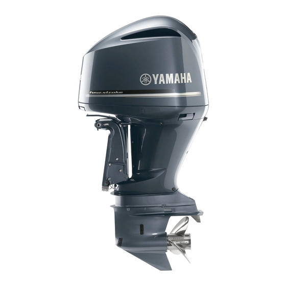
Yamaha F300 Owner's Manual
Hide thumbs Also See for F300:
Table of Contents

Advertisement

Quick Links

OWNER'S MANUAL
q Read this manual carefully before operating this
outboard motor.
F300
F350
LF300
LF350
U.S.A.Edition
LIT-18626-08-14
6AW-28199-14

Advertisement

Table of Contents
loading

Summary of Contents for Yamaha F300

  • Page 1 F300 F350 LF300 LF350 OWNER’S MANUAL U.S.A.Edition q Read this manual carefully before operating this LIT-18626-08-14 outboard motor. 6AW-28199-14...
  • Page 2 EMU25062 ZMU01690 Read this manual carefully before operating this outboard motor. Keep this manual onboard in a waterproof bag when boating. This manual should stay with the outboard motor if it is sold.
  • Page 3 Therefore some items may not tain maximum enjoyment from your new apply to every model. Yamaha. If you have any question about the EMU25111 operation or maintenance of your outboard motor, please consult a Yamaha dealer.
  • Page 4: Table Of Contents

    Table of contents Safety information......1 Digital electronic control requirements ....... 16 Outboard motor safety ....1 Battery requirements..... 16 Propeller..........1 Specifications of Battery....16 Rotating parts........1 Mounting battery ......16 Hot parts ........... 1 Multiple batteries ......16 Electric shock ........
  • Page 5 Table of contents and tilt model ........ 39 Install cowling ........58 Top cowling lock lever Checking power trim and tilt (turn type) ........39 system........... 59 Flushing device ....... 40 Battery ..........60 Fuel filter/Water separator....40 Filling fuel........60 Instruments and indicators ....
  • Page 6 Cleaning the outboard motor ..87 IMPORTANT WARRANTY Checking painted surface of INFORMATION IF YOU USE motor..........87 YOUR YAMAHA OUTSIDE Periodic maintenance....87 THE USA OR CANADA .... 116 Replacement parts ......88 Maintenance interval guidelines..88 Maintenance chart 1 ....... 89 Maintenance chart 2 .......
  • Page 7: Safety Information

    Safety information EMU33622 tor and the clamp bracket when the motor is Outboard motor safety trimmed or tilted. Keep body parts out of this Observe these precautions at all times. area at all times. Be sure no one is in this EMU36500 area before operating the power trim and tilt Propeller...
  • Page 8: Gasoline Exposure And Spills

    Personal flotation devices cording to the boat manufacturers instruc- Have an approved personal flotation device tions. Overloading or incorrect weight (PFD) on board for every occupant. Yamaha distribution can compromise the boats han-...
  • Page 9: Avoid Collisions

    Safety information dling and lead to an accident, capsizing or boating in hazardous weather. swamping. EMU33800 Accident reporting EMU33771 Avoid collisions Boat operators are required by law to file a Scan constantly for people, objects, and Boating Accident Report with their state other boats.
  • Page 10: Passenger Training

    Safety information go to boatus.org. United States Power Squadrons 1-888-FOR-USPS (1-888-367-8777) EMU33880 Passenger training www.usps.org Make sure at least one other passenger is trained to operate the boat in the event of an Boat Owners Association of The United emergency. States EMU33890 1-800-336-BOAT (1-800-336-2628)
  • Page 11: Steering And Sailing Rules And Sound Signals

    Safety information EMU33700 vessels try to avoid each other. If that is the Steering and sailing rules and sound case, both vessels become “ Give-Way ” signals vessels. Whenever two vessels on the water meet EMU25521 Rules when encountering vessels one another, one vessel has the right-of- There are three main situations that you may way;...
  • Page 12: Other Special Situations

    Safety information EMU25531 Other special situations There are three other rules you should be aware of when driving your boat around oth- er vessels. Narrow channels and bends When navigating in narrow channels, you should keep to the right when it is safe and practical to do so.
  • Page 13 Safety information Reading buoys and other markers The waters of the United States are marked for safe navigation by the lateral system of buoyage. Simply put, buoys and markers have an arrangement of shapes, colors, numbers and lights to show which side of the buoy a boater should pass on when navigat- ing in a particular direction.
  • Page 14 Safety information ZMU01708...
  • Page 15: General Information

    Outboard motor serial number TIP: The outboard motor serial number is Consult your Yamaha dealer if you have any stamped on the label attached to the port questions concerning the digital electronic side of the clamp bracket.
  • Page 16: Key Number

    General information EMU25190 Key number If a main key switch is equipped with the mo- tor, the key identification number is stamped on your key as shown in the illustration. Record this number in the space provided for reference in case you need a new key. ZMU05958 1.
  • Page 17: Read Manuals And Labels

    Read any manuals supplied with the boat. ● Read all labels on the outboard motor and the boat. ● If you need any additional information, contact your Yamaha dealer. EMU33831 Warning labels If these labels are damaged or missing, contact your Yamaha dealer for replacements. ZMU05942...
  • Page 18 General information ZMU05741 EMU33850 Other labels ZMU05710...
  • Page 19 General information EMU35132 Electrical hazard Symbols The following symbols mean as follows. Notice/Warning ZMU05666 ZMU05696 Read Owner’s Manual ZMU05664 Hazard caused by continuous rotation ZMU05665...
  • Page 20: Specifications And Requirements

    Specifications and requirements EMU35950 Engine: Specifications Type: TIP: 4-stroke V “*” means, select the engine oil referring to Displacement: 5330.0 cm the chart of engine oil paragraph. For further Bore × stroke: information, see page 18. 94.0 × 96.0 mm (3.70 × 3.78 in) EMU2821C Ignition system: Dimension:...
  • Page 21: Installation Requirements

    Specifications and requirements LF300TR XL API GL-5 LF350TR XL Gear oil quantity: F300TR 1.520 L Fuel and oil: Recommended fuel: (1.607 US qt, 1.338 Imp.qt) F300TR Regular unleaded gasoline F350TR 1.520 L F350TR Premium unleaded gasoline (1.607 US qt, 1.338 Imp.qt) LF300TR Regular unleaded gasoline LF300TR 1.310 L LF350TR Premium unleaded...
  • Page 22: Digital Electronic Control Requirements

    Your dealer or other person experienced in Consult your Yamaha dealer for setting. proper rigging should mount the motor using EMU25694 correct equipment and complete rigging in- Battery requirements structions.
  • Page 23: Propeller Selection

    Counter rotation models rotate counterclock- appropriate. wise. Counter rotation models are typically Your Yamaha dealer can help you select the used in multiple motor setups and are right propeller for your boating needs. Select marked with an “L” on the gear case above a propeller that will allow the engine to reach the anti-ventilation plate.
  • Page 24: Engine Oil Requirements

    Excluding oil filter: ing occurs, use a different brand of gasoline 6.3 L (6.66 US qt, 5.54 Imp.qt) or premium unleaded fuel. Yamaha re- Amount of adding engine oil (at Periodic comends that you use alcohol-free (see maintenance) Including oil filter: Gasohol) gasoline whenever possible.
  • Page 25: Ring Free Fuel Additive

    10% and the fuel Ring Free Fuel Additive, available from meets the minimum octane ratings. E85 is a your Yamaha dealer. Ring Free Fuel Addi- fuel containing 85% ethanol and must not be tive has repeatedly proven its ability to clean used in your outboard motor.
  • Page 26: Motor Disposal Requirements

    This label is attached to the clamp bracket or with clip. the swivel bracket. Spare parts, such as an extra set of spark ● plugs. Consult your Yamaha dealer for details. EMU25221 Emission control information EMU25230 North American models This engine conforms to U.S. Environmental Protection Agency (EPA) regulations for ma- rine SI engines.
  • Page 27: Star Labels

    Specifications and requirements EMU25280 One Star—Low Emission The one-star label identifies engines that meet the Air Resources Board’s 2001 ex- haust emission standards. Engines meeting these standards have 75% lower emissions than conventional carbureted two-stroke en- gines. These engines are equivalent to the U.S.
  • Page 28 Specifications and requirements these standards have 65% lower emissions than One Star-Low-Emission engines. ZMU01704 EMU33861 Four Stars—Super Ultra Low Emission The four-star label identifies engines that meet the Air Resources Board’s Sterndrive and Inboard marine engine 2009 exhaust emission standards. Personal Watercraft and Outboard marine engines may also comply with these standards.
  • Page 29: Components

    EMU2579J Components diagram TIP: * May not be exactly as shown; also may not be included as standard equipment on all mod- els. F300, F350, LF300, LF350 ZMU05813 1. Top cowling 2. Anti-cavitation plate 3. Propeller* 4. Cooling water inlet 5.
  • Page 30 Components Single station models ZMU06310 1. Digital electronic control (side-mount type)* 2. Clip 3. Engine stop button/Engine shut-off switch 4. Switch panel (for use with side-mount type)* 5. Digital electronic control (single type)* 6. Switch panel (for use with single type)* 7.
  • Page 31 Components Dual station models / main station ZMU05974 1. Digital electronic control (single type)* 2. Switch panel (for use with single type)* 3. Digital electronic control (twin type)* 4. Switch panel (for use with twin type)* 5. Clip 6. Engine shut-off switch 7.
  • Page 32 Components Dual station models / sub station ZMU05975 1. Digital electronic control (single type)* 2. Switch panel (for use with single type)* 3. Digital electronic control (twin type)* 4. Switch panel (for use with twin type)* 5. Clip 6. Engine shut-off switch 7.
  • Page 33: Digital Electronic Control

    Components ZMU05429 EMU35941 1. Tachometer unit (Square type)* Digital electronic control 2. Tachometer unit (Round type)* The digital electronic control actuates the 3. Speedometer unit (Square type)* shifter, the throttle and remote electrical op- 4. Speed & fuel meter unit (Square type)* erations.
  • Page 34: Digital Electronic Control-Active Indicator

    Components ZMU05959 ZMU06225 1. Control lever 1. Control lever 2. Digital electronic control-active indicator 2. Neutral interlock trigger 3. Digital electronic control-alert indicator 3. Digital electronic control-alert indicator 4. Free throttle switch 4. Digital electronic control-active indicator 5. Throttle friction adjuster 5.
  • Page 35: Digital Electronic Control-Alert Indicator

    Components EMU34983 Digital electronic control-alert indicator The digital electronic control-alert indicator lights when trouble occurs in the connection between the digital electronic control and outboard motor. Consult your Yamaha deal- er for details. ZMU05888 ZMU06227 ZMU05890 ZMU05889 ZMU05966 1. Digital electronic control-active indicator The digital electronic control-active indicator on the selected station lights.
  • Page 36: Control Lever

    Components ZMU05960 ZMU06228 1. Digital electronic control-alert indicator EMU35821 Control lever Moving the lever forward from the neutral po- sition engages forward gear. Pulling the le- ver back from neutral engages reverse. The engine will continue to run at idle until the le- ver is moved 22.5°...
  • Page 37: Free Throttle Switch

    Components 22.5˚ ZMU06285 ZMU06232 Single type 1. Neutral interlock trigger EMU35831 Free throttle switch In neutral, keep this switch pressed, move the control lever forward, and release the switch after the digital electronic control-ac- tive indicator starts blinking. While the indi- cator blinks, you can open or close the throttle.
  • Page 38: Throttle Friction Adjuster

    Components Twin type 22.5 ZMU05962 ZMU05882 1. Fully open 2. Fully closed 22.5 3. Free accelerator The free throttle switch can only be used when the control lever is in the neutral posi- tion. During operation the digital electronic con- trol-active indicator changes from continu- ously lit to blinking.
  • Page 39: Station Selector Switch

    Components EWM01770 Twin type WARNING If the friction is too small, the control le- ● ver could move freely and cause an ac- cident. Do not overtighten the friction adjuster. ● If there is too much resistance, it could be difficult to move the control lever, which could result in an accident.
  • Page 40: Engine Selector Switch

    Components running away under power. EWM01790 WARNING Attach the engine shut-off cord to a se- ● cure place on your clothing, or your arm or leg while operating. Do not attach the cord to clothing that ● could tear loose. Do not route the cord where it could become entangled, pre- ZMU05976 venting it from functioning.
  • Page 41: Main Switch

    Components START START ZMU05818 ZMU05980 ZMU05978 ZMU05981 1. Cord 1. Cord 2. Clip 2. Clip 3. Engine shut-off switch 3. Engine shut-off switch Sub station EMU35781 Main switch The main switch controls the ignition system; its operation is described below. Only equipped with the main station.
  • Page 42: Starter Button

    Components automatically to the “ ” (on) position. Triple type Single type START START START START ZMU05982 ZMU06245 EMU35730 Starter button To start the engine with the electric starter, START push the black button. Only equipped on the sub station. Single type ZMU04567 Twin type...
  • Page 43: Engine Stop Button

    Components Triple type Triple type ZMU05985 ZMU05988 EMU35740 EMU35152 Engine stop button Power trim and tilt switch on digital To stop the engine, push the red button. Only electronic control equipped on the sub station. The power trim and tilt system adjusts the Single type outboard motor angle in relation to the tran- som.
  • Page 44: Power Trim And Tilt Switch On Bottom Engine Cowling

    Components ZMU05823 ZMU05822 EMU26153 EMU35851 Power trim and tilt switch on bottom Power trim and tilt switches engine cowling The power trim and tilt system adjusts the outboard motor angle in relation to the tran- The power trim and tilt switch is located on som.
  • Page 45: Tilt Limiter

    TIP: port and fall. If the motor cannot be trail- Consult your Yamaha dealer about changing ered in the normal running position, use the setting. an additional support device to secure it EMU35030 in the tilt position.
  • Page 46: Flushing Device

    Components top cowling and the bottom cowling is even all around the cowling. If the top cowling is loose or the gap is not even, reinstall the cowling. EMU26460 Flushing device This device is used to clean the cooling wa- ter passages of the motor using a garden hose and tap water.
  • Page 47 ● when the gear shift is in neutral. If the alert system has activated, stop the ● engine and consult a Yamaha dealer im- mediately. TIP: Adding an in-line 10-micron fuel filter has been show to greatly reduce the chance of fuel contamination problems.
  • Page 48: Instruments And Indicators

    5. Cooling water/engine temperature will be available. For the optional sensor, 6. Water detection-alert indicator consult your Yamaha dealer. The tachome- 7. Battery voltage ter unit is available in round or square types. 8. Oil pressure (4-stroke models)
  • Page 49: Start-Up Checks

    If the buzzer sounds and the water sep- The default engine idle speed is reset au- ● arator-alert indicator blinks, consult your tomatically when the display is switched to Yamaha dealer immediately. the normal display. The default engine idle...
  • Page 50: Low Oil Pressure-Alert

    Instruments and indicators speed is also reset automatically when the Yamaha dealer. engine is turned off or when the engine ECM01601 NOTICE speed exceeds 3000 r/min. Do not continue to run the engine if the When warming up a cold engine, the troll- ●...
  • Page 51: Water Separator Alert

    (fuel filter) while cruising. In such an event, stop the engine immediately and see page 107 of this manu- al to drain the water from the fuel filter. Get back to the port soon and consult a Yamaha dealer immediately. ZMU05425 ZMU05423...
  • Page 52: Command Link Multifunction Speed & Fuel Meters

    For the optional sensors, consult your Yamaha dealer. The speed & fuel meter unit is available in round or square types. Check your speed & fuel meter unit type for operation information.
  • Page 53: Command Link Multifunction Speedometers

    For the optional sensors, consult your Yamaha dealer. The fuel management meter has the func- After the main switch is first turned on, all the tions of fuel flow meter, total consumption displays come on as a test.
  • Page 54 Instruments and indicators ation. For more information, see the operation manual originally supplied with the meter. ZMU05438 1. Set button 2. Mode button ZMU05439 1. Fuel flow meter 2. Multifunction display...
  • Page 55: Engine Control System

    Alert system ECM00091 NOTICE Do not continue to operate the engine if a alert device has activated. Consult your Yamaha dealer if the problem cannot be located and corrected. EMU35183 ZMU05891 Digital Electronic Control alert If during operation of the outboard motor any...
  • Page 56 Engine control system START START ZMU05422 ZMU05827 The buzzer will sound. ● Main station START START START ZMU05989 Sub station ZMU06297 ZMU05990 ZMU04583 ZMU05991...
  • Page 57: Low Oil Pressure Alert

    If the overheat alert system of one engine ac- is correct and the alert device does not tivates, the engine will slow down. To switch switch off, consult your Yamaha dealer. off the alert activation on the engine not af- Twin engine drive or triple engine drive us-...
  • Page 58: Installation

    EMU26931 Mounting height (boat bottom) motor. The mounting height of your outboard motor Consult your Yamaha dealer or boat manu- affects its efficiency and reliability. If it is facturer for further information on determin- mounted too high, propeller ventilation may...
  • Page 59 Test runs at differ- ent heights can help determine the optimum mounting height. Consult your Yamaha deal- er or boat manufacturer for further informa- tion on determining the proper mounting height.
  • Page 60: Operation

    Operation EMU36380 TIP: First-time operation Failure to follow the break-in procedure EMU36390 could result in reduced engine life or even Fill engine oil severe engine damage. Run the engine in The engine is shipped from the factory with- the water, under load (in gear with a propel- out engine oil.
  • Page 61: Fuel Level

    Check that the fuel filter is clean and free of water. If enough water to raise the float ring ZMU05852 is found in the fuel, or if a significant amount of debris is found, the fuel tank should be checked and cleaned by a Yamaha dealer. ZMU05853...
  • Page 62: Controls

    Operation Single type ZMU05854 ZMU04565 EMU37670 Controls Turn the steering wheel full-right and full- ● left. Make sure operation is smooth and unrestricted throughout the whole range with no binding or excessive free play. Operate the throttle levers several times to ●...
  • Page 63: Engine Oil

    Check the oil level using the dipstick to 1. Cord be sure the level falls between the upper 2. Clip and lower marks. Consult your Yamaha 3. Engine shut-off switch dealer if the oil level is out of specified Triple type level or if it appears milky or dirty.
  • Page 64: Engine

    After installing, check the fitting of the top cowling by pushing it with both hands. If the ZMU06057 top cowling is loose, have it repaired by your 1. Fitting Yamaha dealer. 2. Flushing device EMU36940 Install cowling Be sure that all cowling lock levers are...
  • Page 65: Checking Power Trim And Tilt System

    Operation ZMU05868 EMU35243 1. Tilt rod Checking power trim and tilt system 2. Trim rods EWM01930 WARNING Use the tilt support lever to lock the mo- Never get under the lower unit while it ● tor in the up position. Operate the tilt is tilted, even when the tilt support lever down switch briefly so the motor is sup- is locked.
  • Page 66: Battery

    Operation doctor immediately. If gasoline spills on your skin, wash with soap and wa- ter. If gasoline spills on your clothing, change your clothes. Stop the engine. Be sure you are in a well-ventilated out- door area, either securely moored or trailered.
  • Page 67: Change Of Station

    Operation EMU27492 Starting engine EWM01600 WARNING Before starting the engine, make sure that the boat is tightly moored and that you can steer clear of any obstructions. Be sure there are no swimmers in the wa- ter near you. EMU35866 Procedure for single station models 1.
  • Page 68 Operation ZMU04628 ZMU06236 START START ZMU05829 ZMU05828 Attach the engine shut-off cord to a se- cure place on your clothing, or your arm or leg. Then install the clip on the other end of the cord into the engine shut-off switch.
  • Page 69 Operation START ZMU05830 Turn the main switch to “ ” (start), and hold it for a maximum of 5 seconds. START START ZMU05994 Immediately after the engine starts, re- ZMU06246 lease the main switch to return it to “ ” (on).
  • Page 70 Operation EMU35922 onds, the battery will be quickly dis- Procedure for dual station models (main charged, thus making it impossible to station) start the engine. The starter can also Place the control lever in “ ” (neutral). be damaged. If the engine will not TIP: start after 5 seconds of cranking, re- The start-in-gear protection device prevents...
  • Page 71 Operation sub station. Station change is only pos- sible when all control levers have been set to “ ” (neutral). Make sure that the digital electronic control-active indicator of the sub station lights. ZMU05997 Push the starter button to start the mo- tor.
  • Page 72: Checks After Starting Engine

    Operation er the cooling water inlet on the lower case or the cooling water pilot hole is blocked. Consult your Yamaha dealer if the problem cannot be located and cor- rected. ZMU05984 ZMU05848 Check that no water leaks from the joints be- tween the exhaust cover, cylinder head, and body cylinder.
  • Page 73: Selecting Outboard Motor (Triple Engine)

    Operation shut-off switch. EMU35880 Selecting outboard motor (triple engine) After all engines have started, set all control levers to Neutral. Push the engine selector switch repeatedly to change the digital elec- tronic control-active indicator and select the desired engine. ZMU05999 Operate the port side engine using the port ●...
  • Page 74: Shifting

    Operation Operate the port side engine using the port ● side control lever. The center engine runs at the idling speed. ● Operate the starboard side engine using ● the starboard side control lever. Push the engine selector switch twice to operate the center engine.
  • Page 75 Operation equipped). slows to idle speed. ZMU06239 ZMU06285 1. Neutral interlock trigger Move the control lever firmly and crisply forward (for forward gear) or backward (for reverse gear) 22.5° (a detent can felt). 22.5˚ 22.5˚ ZMU05832 After the engine is at idle speed in gear move the control lever firmly and crisply into the neutral position.
  • Page 76: Stopping Boat

    Operation pipe due to the wave action, causing en- gine trouble. ZMU05829 EMU31742 Stopping boat EWM01510 WARNING Do not use the reverse function to slow ● down or stop the boat as it could cause you to lose control, be ejected, or im- pact the steering wheel or other parts of the boat.
  • Page 77 Operation Operate the port side engine using the port ● side control lever. Operate the starboard side engine using ● the starboard side control lever. Operating the port side engine and center engine ZMU06004 Operate the port side engine using the port ●...
  • Page 78 Operation Operating the center engine and star- board side engine ZMU06010 Operate the center engine using the port ● ZMU06008 side control lever. ZMU06009 Operate the center engine using the port ● side control lever. Operate the starboard side engine using ●...
  • Page 79: Boat Direction

    Operation EMU35901 Boat direction The illustrations below indicate the boat direction when operating the three outboard motors. When using the port side engine, center engine and starboard side engine ZMU06011 :Boat direction and turning force The size of the arrow is proportional to the turning force. :Propulsion...
  • Page 80 Operation When using the port side engine and starboard side engine ZMU06012 :Boat direction and turning force The size of the arrow is proportional to the turning force. :Propulsion...
  • Page 81 Operation When using the center engine ZMU06013 :Boat direction and turning force The size of the arrow is proportional to the turning force. :Propulsion...
  • Page 82: Stopping Engine

    Operation EMU27821 Stopping engine Before stopping the engine, first let it cool off for a few minutes at idle or low speed. Stop- ping the engine immediately after operating at high speed is not recommended. EMU35801 Procedure for single station models Turn the main switch to “...
  • Page 83: Trimming Outboard Motor

    Operation cause boat instability and can make steering the boat more difficult. This in- creases the possibility of an accident. If the boat begins to feel unstable or is hard to steer, slow down and/or readjust the trim angle. The trim angle of the outboard motor helps determine the position of the bow of the boat in the water.
  • Page 84: Adjusting Boat Trim

    Operation angle can cause loss of control. If equipped with a power trim and tilt ● switch located on the bottom cowling, use the switch only when the boat is at a complete stop with the engine off. Do not adjust the trim angle with this switch while the boat is moving.
  • Page 85: Tilting Up And Down

    Operation plane. TIP: Bow Up Depending on the type of boat, the outboard Too much trim-out puts the bow of the boat motor trim angle may have little effect on the too high in the water. Performance and econ- trim of the boat when operating. omy are decreased because the hull of the EMU27944 Tilting up and down...
  • Page 86: Procedure For Tilting Up (Power Trim And Tilt Models)

    Operation stopped 30 seconds or more. EMU35505 Procedure for tilting up (power trim and tilt models) The main switch must be “ ” (on) for the power trim and tilt switch on the dig- ital electronic control to operate. Place the control lever in neutral. ZMU06280 ZMU06236 ZMU05837...
  • Page 87: Procedure For Tilting Down (Power Trim And Tilt Models)

    Operation ZMU05839 Set the tilt support lever to support the engine. WARNING! After tilting the outboard motor, be sure to support it with the tilt support knob or tilt sup- port lever. Otherwise the outboard motor could fall back down suddenly if oil in the power trim and tilt unit or in the power tilt unit loses pressure.
  • Page 88: Shallow Water

    Operation ZMU05856 ZMU05841 Push the power trim and tilt switch “ ” (down) to lower the outboard motor to the desired position. ZMU06021 ZMU06258 ZMU05842 EMU28061 Shallow water ZMU05840 EMU32871 Power trim and tilt models The outboard motor can be tilted up partially to allow operation in shallow water.
  • Page 89 Operation unit could be damaged. Do not tilt the outboard motor up so ● that the cooling water inlet on the lower unit is above the surface of the water when setting up for and cruising in shallow water. Otherwise severe dam- age from overheating can result.
  • Page 90: Cruising In Other Conditions

    Cruising in muddy, turbid, or acidic water Yamaha strongly recommends that you use the optional chromium-plated water pump kit (see page 19) if you use the outboard motor in acidic water or water with a lot of sediment in it, such as muddy or turbid (cloudy) water.
  • Page 91: Maintenance

    Leaking fuel is a fire hazard. When trans- TIP: porting and storing the outboard motor, The last time you use your Yamaha outboard close the fuel cock to prevent fuel from motor before storing it for a prolonged peri- leaking. Never get under the engine while od, add one ounce of Yamaha Fuel Condi- it is tilted.
  • Page 92: Lubrication

    98. Inspect the oil for the pres- ence of water that indicates a leaky seal. Seal replacement should be performed by an authorized Yamaha dealer prior to use. Grease all grease fittings. For further de- tails, see page 92.
  • Page 93: Cleaning The Outboard Motor

    Yamaha dealer or other qualified [ECM00541] mechanic do the work. TIP: The procedures involve disassembling When flushing the engine with the boat in ●...
  • Page 94: Replacement Parts

    Yamaha marine dealership. A service manual is available for purchase through your Yamaha dealer for owners who have the mechanical skills, tools, and other equipment necessary to perform mainte- nance not covered by this owner’s manual.
  • Page 95: Maintenance Chart 1

    The “ ” symbol indicates the check-ups which you may carry out yourself. The “ ” symbol indicates work to be carried out by your Yamaha dealer. Initial Every 20 hours Item...
  • Page 96 Maintenance Initial Every 20 hours Item Actions hours (1 hours (3 hours (5 months) year) years) years) Engine oil Replacement Engine Oil filter (car- Replacement tridge) Fuel filter (can be dis- Inspection or replace- assembled) ment as necessary Fuel line(High pres- Inspection sure) Fuel line(High pres-...
  • Page 97: Maintenance Chart 2

    Inspection Main switch/stop Inspection or replace- switch ment as necessary Wire harness connec- Inspection or replace- tions/Wire coupler con- ment as necessary nections (Yamaha) Meter/gauge Inspection EMU34451 Maintenance chart 2 Every Item Actions 1000 hours Guide exhaust/exhaust Inspection or replace-...
  • Page 98: Greasing

    Maintenance EMU28932 Greasing Yamaha marine grease (Water resistant grease) F300, F350, LF300, LF350 ZMU05859...
  • Page 99: Cleaning And Adjusting Spark Plug

    Instead, take the outboard motor to a Remove the bolts to move the plate. Yamaha dealer. You should periodically re- move and inspect the spark plug because heat and deposits will cause the spark plug to slowly break down and erode.
  • Page 100 Maintenance 2. Spark plug I.D. mark (NGK) 3. Spark plug part number Spark plug gap: 1.0–1.1 mm (0.039–0.043 in) When fitting the plug, wipe off any dirt from the threads, and then screw it in to the correct torque. ZMU05903 Spark plug torque: Remove the spark plug.
  • Page 101 Maintenance ZMU05901 Bolt tightening torque: 8.0 Nm (0.8 kgf-m, 5.8 ft-lb) 12. Install the rear cover, and tighten the ZMU05929 bolts. ZMU05900 Bolt tightening torque: 8.0 Nm (0.8 kgf-m, 5.8 ft-lb) ZMU05932 13. Be sure to fit the 4 positions during in- stallation.
  • Page 102: Inspecting Idling Speed

    3 months, and ev- ery 100 hours or at 1-year intervals there- after. Otherwise the engine will wear quickly. ZMU05930 Consult your Yamaha dealer for replace- ment of the engine oil filter and change of the engine oil. EMU29112 Checking wiring and connectors Check that each grounding wire is properly ●...
  • Page 103: Checking Propeller

    Maintenance EMU29173 Checking propeller EWM01880 WARNING You could be seriously injured if the en- gine accidentally starts when you are near the propeller. Before inspecting, removing, or install- ● ing the propeller, place the shift control in neutral, turn the main switch to “ ”...
  • Page 104: Installing Propeller

    WARNING Be sure the outboard motor is securely ● Apply Yamaha marine grease or a cor- fastened to the transom or a stable rosion resistant grease to the propeller stand. You could be severely injured if shaft.
  • Page 105 Consult a level plug. Yamaha dealer for repair of the lower Tightening torque: unit seals. [ECM00711] 9 Nm (0.9 kgf-m, 6.6 ft-lb)
  • Page 106: Inspecting And Replacing Anode(S)

    Tightening torque: 2 Nm (0.2 kgf-m, 0.2 ft-lb) EMU29312 Inspecting and replacing anode(s) Yamaha outboard motors are protected from corrosion by sacrificial anodes. Inspect the external anodes periodically. Remove scales from the surfaces of the anodes. Consult a Yamaha dealer for replacement of external anodes.
  • Page 107: Connecting The Battery

    WARNING! Bad Connecting an accessory battery (optional) connections can produce shorting or If connecting an accessory battery, con- arcing and cause an explosion. sult your Yamaha dealer about correct [EWM01910] wiring. For the fuse size, see ABYC (E- EMU35493 11).
  • Page 108 Maintenance Single engine Twin engines ZMU05939 ZMU05941 1. Isolator lead with circuit protection 1. Starboard side engine 2. Red cable 2. Port side engine 3. Black cable 3. Red cable 4. Fuse 4. Black cable 5. Battery for accessories 5. Isolator lead with circuit protection 6.
  • Page 109: Disconnecting The Battery

    Maintenance Triple engines Disconnect the negative cable(s) from the negative (-) terminal. NOTICE: Al- ways disconnect all negative (-) ca- bles first to avoid a short circuit and damage to the electrical system. [ECM01940] Disconnect the positive cable(s) and re- move the battery from the boat.
  • Page 110: Trouble Recovery

    Q. Has fuel pump malfunctioned? If your outboard motor requires repair, bring A. Have serviced by a Yamaha dealer. it to your Yamaha dealer. If the engine trouble-alert indicator is flash- Q. Are spark plug(s) fouled or of incorrect ing, consult your Yamaha dealer.
  • Page 111 Q. Is fuel contaminated or stale? A. Fill tank with clean, fresh fuel. Q. Is carburetor clogged? A. Have serviced by a Yamaha dealer. Q. Is fuel filter clogged? A. Clean or replace filter. Q. Is fuel joint connection incorrect? A.
  • Page 112 Q. Is fuel system obstructed? Q. Is water pump or thermostat faulty? A. Check for pinched or kinked fuel line or A. Have serviced by a Yamaha dealer. other obstructions in fuel system. Q. Is there excess water in fuel filter cup? Q.
  • Page 113: Temporary Action In Emergency

    When using only one or two en- gines in an emergency, be sure to keep the Q. Is steering pivot loose or damaged? unused engine(s) tilted up and operate the A. Tighten or have serviced by a Yamaha other engine(s) at low speed. dealer. ECM01730...
  • Page 114: Replacing Fuse

    3. Spare fuse (10 A, 15 A, 20 A, 30 A, 60 A) of wire could allow excessive current flow. This could cause electric system damage and a fire hazard. Consult your Yamaha dealer if the new fuse immediately blows again. ZMU05875 1. Fuel feed pump fuse (10 A) 2.
  • Page 115: Power Trim And Tilt Will Not Operate

    If the engine cannot be tilted up or down with the power trim and tilt because of a dis- charged battery or a failure with the power trim and tilt unit, consult your Yamaha deal- 1. Water separator-alert indicator EMU35073 Stop the engine.
  • Page 116 Trouble Recovery ZMU05895 Unscrew the filter cup from the filter housing. NOTICE: Be careful not to twist the water detection switch lead when unscrewing the filter cup. [ECM01960] ZMU05892 Disconnect the water detection switch coupler. NOTICE: Be careful not to get any water on the water detection switch coupler, otherwise a malfunc- tion could occur.
  • Page 117: Treatment Of Submerged Motor

    EMU33501 Treatment of submerged motor If the outboard motor is submerged, immedi- ately take it to a Yamaha dealer. Otherwise ZMU05895 some corrosion may begin almost immedi- ately. NOTICE: Do not attempt to run the...
  • Page 118: Consumer Information

    Consumer information EMU29811 Important warranty information for U.S.A. and Canada...
  • Page 119 Consumer information...
  • Page 120: Yamaha Motor

    Consumer information EMU29830 YAMAHA MOTOR CORPORATION, U.S.A. FOUR-STROKE OUTBOARD MOTOR THREE-YEAR LIMITED WARRANTY...
  • Page 121 Consumer information...
  • Page 122: Important Warranty Information If You Use Your Yamaha Outside The Usa Or Canada

    Consumer information EMU29841 IMPORTANT WARRANTY INFORMATION IF YOU USE YOUR YAMAHA OUTSIDE THE USA OR CANADA...
  • Page 124 Printed in Japan April 2008–0.1 × 1 ! Printed on recycled paper...

This manual is also suitable for:

F500Lf300Lf350F350

Table of Contents