
Subscribe to Our Youtube Channel
Related Manuals for Boser HS-3000/4M


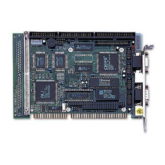
Summary of Contents for Boser HS-3000/4M
- Page 1 HS-3000/4M 386 ISA Bus SBC •CRT/Panel•RS-232/422/485•4 COM• •PC/104•DOC•WDT•Single +5V• ISA Bus Industrial Single Board Computer...
- Page 2 The accuracy of contents in this manual has passed thorough checking and review before publishing. BOSER Technology Co., Ltd., the manufacturer and publisher, is not liable for any infringements of patents or other rights resulting from its use. The manufacturer will not be responsible for any direct, indirect, special, incidental or consequential damages arising from the use of this product or documentation, even if advised of the possibility of such damage(s).
-
Page 3: Table Of Contents
Table of Contents Chapter 1 General Description......1 1.1 Major Features ..............2 1.2 Specifications ..............3 1.3 Board Dimensions............4 Chapter 2 Unpacking ..........5 2.1 Opening the Delivery Package........5 2.2 Inspection................5 Chapter 3 Hardware Installation ......7 3.1 Before Installation ............7 3.2 Board Layout .............. - Page 4 Chapter 4 AMI BIOS Setup.........27 4.1 Starting Setup ..............27 4.2 Using Setup..............28 4.3 Main Menu ............... 29 4.4 Standard CMOS Setup ........... 30 4.5 Advanced CMOS Setup ..........31 4.6 Advanced Chipset Setup ..........32 4.7 PCI / Plug And Play Setup ..........33 4.8 Peripheral Setup.............
- Page 5 Please wear and connect the strap before handle the HS-3000/4M to ensure harmlessly discharge any static electricity through the strap. Please use an anti-static pad when putting down any components or parts or tools outside the computer.
- Page 6 This page is intentionally left blank.
-
Page 7: Chapter 1 General Description
Chapter 1 General Description The HS-3000/4M is ISA Bus ALi M6117C chipset industrial single board computer. The board design combine together with all necessary input and output effects interfaces which makes it an ideal all-in-one industrial single board computer. The board design with 40MHz Bus clock rate architecture. -
Page 8: Major Features
WDT is designed with pure hardware and doesn’t need any arithmetical functions of a real-time clock chip. This ensures the reliability in an unmanned or standalone system. Major Features The HS-3000/4M comes with the following features: ® Intel 386SX compatible CPU One SIMM socket with a max. -
Page 9: Specifications
Specifications CPU: 386SX-40 embedded in ALi M6117C chipset Bus Interface: ISA Bus Memory: One SIMM socket with a max. capacity of 16MB and 4MB RAM onboard Chipset: ALi M6117C I/O Chipset: SMC 37C669 x 2 VGA: C&T 65545 with 1MB memory supporting CRT/Panel displays up to 1024 x 768 at 16 colors IDE: Two IDE disk drives supporting LBA mode and with a transfer rate of 11MB/sec. -
Page 10: Board Dimensions
Board Dimensions... -
Page 11: Chapter 2 Unpacking
Opening the Delivery Package The HS-3000/4M is packed in an anti-static bag. The board has components that are easily damaged by static electricity. Do not remove the anti-static wrapping until proper precautions have been taken. - Page 12 It is recommended that you keep all the parts of the delivery package intact and store them in a safe/dry place for any unforeseen event requiring the return shipment of the product. In case you discover any missing and/or damaged items from the list of items, please contact your dealer immediately.
-
Page 13: Chapter 3 Hardware Installation
Chapter 3 Hardware Installation This chapter provides the information on how to install the hardware using the HS-3000/4M. This chapter also contains information related to jumper settings of switch, watchdog timer, and the DiskOnChip address selection etc. Before Installation After confirming your package contents, you are now ready to install your hardware. -
Page 14: Board Layout
Board Layout... -
Page 15: Jumper List
Jumper List Jumper Definition Setting Page COM 4 Use RS-232 or RS-422/485 Select: Open RS-232 IRQ12 Enabled/Disabled Select: Enabled Short WDT Active Type Select: Reset System Short 1-2 JP11 DiskOnChip Address Select: D000 Short 1-2 RS-422/485 Receiver Enabled/Disabled Select: JP12 Short 1-2 Always Enabled RS-422/485 Transmitter Enabled/Disabled... -
Page 16: Diskonchip Address Setting
FORMAT, SYS, COPY, XCOPY, DISCOPY and DISKCOMP etc. The U9 location onboard the HS-3000/4M is the DiskOnChip module socket. Jumper JP11 assigns the address setting of the installed module. Setting the 8 pins of JP11 allows you to select the starting memory address of the DiskOnChip (D.O.C.). - Page 17 JP9: Watchdog Timer Active Type Select Description Short 1-2 (default) System Reset Short 2-3 Active NMI Open Disabled JP14: Watchdog Timer Out Period Select Period PINS 1-2 PINS 3-4 PINS 5-6 PINS 7-8 1 sec Open Open Short Open (default) 2 sec Open Open...
-
Page 18: Vga Controller
VGA Controller The onboard C&T 65545 CRT/Panel display controller provides up to 1024 x 768 at 16 colors resolution. The HS-3000/4M provides two connection methods of CRT and Panel device. CN18 offers a 15-pin CRT connector, and CN11 offers a 50-pin Panel connector. - Page 19 CN11 Description CN11 Description SHFCLK ENABKL ASHFCLK 3.7.1 Connectors for Standard LCDs Sharp LM64183P (640 x 480 DSTN MONO LCD) Sharp LM64P83(CN1) HS-3000/4M(CN11) Description Description SHFCLK DISP -17V (external power)
- Page 20 Sharp LM64C35P (640 x 480 DSTN STN Color) Sharp LM64C35P(CN1) HS-3000/4M(CN11) Description Description SLFCHK VCON Contrast Adjust DISP...
- Page 21 Sharp LM64C142(640 x 480 DSTN STN Color) Sharp LM64C142(CN1) HS-3000/4M(CN11) Description Description SHFCLK DISP PVDD PVSS PVEE +27V (external power) Sharp LM64C142 (CN2) HS-3000/4M(CN11) Description Description NEC NL8060AC26 (800 x 600 TFT Color) NEC NL8060AC26(CN1) HS-3000/4M(CN11) Description Description Dot Clock...
- Page 22 NEC NL8060AC26(CN1) HS-3000/4M(CN11) Description Description PVCC PVCC PVCC PVCC PVCC PVCC MODE ----...
-
Page 23: Serial Port Connectors
Serial Port Connectors The HS-3000/4M’s CN17, 14, 15 and 16 provide four high speeds NS16C550 compatible USRT with Read/Receive 16 byte FIFO serial ports. CN14, 15, 16: COM 2~COM 4 Connector (5x2 header) PIN Description PIN Description CN17: COM 1 Connector (DB9) -
Page 24: Keyboard & Mouse Connector
Enable by writing the REG.2EFh BIT0=1 Short 7-8 Always Disable Keyboard & Mouse Connector The HS-3000/4M offers two connection methods for keyboard connector, at location CN19 is 5-pin connector, location CN21 is PS/2 6-pin Mini DIN connector. CN19: 5-pin Keyboard Connector... -
Page 25: Speaker Connector
CN20: PS/2 6-pin Mini DIN Mouse Connector Description Mouse Data Mouse Clock Mouse Data Mouse Clock 3.10 Speaker Connector The HS-3000/4M has its own buzzer, and CN5 allows user to connect to the external speaker. CN5: Speaker Connector Description Speaker... -
Page 26: Pci E-Ide Drive Connector
3.11 PCI E-IDE Drive Connector One standard 40-pin header daisy-chain driver connector provides as CN10 with following pin assignment. Total two IDE (Integrated Device Electronics) drivers may connect. CN10: IDE Connector Description Description Reset DATA 7 DATA 8 DATA 6 DATA 9 DATA 5 DATA 10... -
Page 27: Parallel Connector
3.12 Parallel Connector A standard 26-pin flat cable driver connector provides as CN2 with following pin assignment for connection to parallel printer. CN2: Parallel Connector Description Description STROBE Auto Form Feed DATA 0 ERROR# DATA 1 Initialize DATA 2 Printer Select LN# DATA 3 DATA 4 DATA 5... -
Page 28: Floppy Disk Drive Connector
CN6: IDE LED Connector Description HDD Active 3.14 Floppy Disk Drive Connector The HS-3000/4M uses a standard 34-pin header connector, CN7, for floppy disk drive connection. A total of two FDD drives may be connected at any given time. CN7: Floppy Connector... -
Page 29: Flash Rom Type
Short 1-2 28F010 Short 2-3 3.16 System Memory The HS-3000/4M has one SIMM socket, provides 72-pin SIMM module. The memory access time should be 70ns or less. The HS-3000/4M has one SIM socket and 4MB RAM onboard. Memory Type Configuration... - Page 30 NOTE: The PC/104 connector allows direct plugging or stack-through piling of PC/104 modules without requiring the PC/104 mounting kit. CN8: PC/104 64-pin Connector Description Description IOCHECK* RESETDRV IRQ9 DRQ2 -12V NOW* +12V IOCHRDY SMEMW* SA19 SMEMR* SA18 IOW* SA17 IOR* SA16 DACK3* SA15...
- Page 31 CN9: PC/104 40-pin Connector Description Description MEMCS16* SBHE* IOSC16* LA23 IRQ10 LA22 IRQ11 LA21 MSDATA LA20 IRQ15 LA19 IRQ14 LA18 DACK0* LA17 DRQ0 MEMR* DACK5* MEMW* DRQ5 DACK6* DRQ6 SD10 DACK7* SD11 DRQ7 SD12 SD13 MASTER* SD14 SD15...
- Page 32 This page is intentionally left blank.
-
Page 33: Chapter 4 Ami Bios Setup
Chapter 4 AMI BIOS Setup The HS-3200/4M uses Award ISA BIOS for the system configuration. The AMI BIOS setup program is designed to provide the maximum flexibility in configuring the system by offering various options that could be selected for end-user requirements. This chapter is written to assist you in the proper usage of these features. -
Page 34: Using Setup
Using Setup In general, you use the arrow keys to highlight items, press <Enter> to select, use the <PageUp> and <PageDown> keys to change entries, press <F1> for help and press <Esc> to quit. The following table provides more detail about how to navigate in the Setup program using the keyboard. -
Page 35: Main Menu
Main Menu Once you enter the Award BIOS CMOS Setup Utility, the Main Menu will appear on the screen. The Main Menu allows you to select from several setup functions and two exit choices. Use the arrow keys to select among the items and press <Enter> to enter the sub-menu. AMI BIOS Setup Utility –... -
Page 36: Standard Cmos Setup
Standard CMOS Setup The Standard Setup is used for the basic hardware system configuration. The main function is for Data/Time and Floppy/Hard Disk Drive settings. Please refer to the following screen for the setup. When the IDE hard disk drive you are using is larger than 528MB, please set the HDD mode to LBA mode. -
Page 37: Advanced Cmos Setup
Advanced CMOS Setup This section allows you to configure your system for the basic operation. You have the opportunity to select the system’s default speed, boot-up sequence, keyboard operation, shadowing and security. AMIBIOS SETUP – ADVANCED CMOS SETUP (C)2001 American Megatrends, Inc. All Rights Reserved Quick Boot Disabled Available Options:... -
Page 38: Advanced Chipset Setup
Advanced Chipset Setup This section allows you to configure the system based on the specific features of the installed chipset. This chipset manages bus speeds and the access to the system memory resources, such as DRAM and the external cache. It also coordinates the communications between the conventional ISA and PCI buses. -
Page 39: Pci / Plug And Play Setup
PCI / Plug And Play Setup This section describes configuring the PCI bus system. PCI, or Personal Computer Interconnect, is a system that allows I/O devices to operate at speeds nearing the speed the CPU itself uses when communicating with its own special components. This section covers some very technical items and it is strongly recommended that only experienced users should make any changes to the default settings. -
Page 40: Peripheral Setup
Peripheral Setup The IDE hard drive controllers can support up to two separate hard drives. These drives have a master/slave relationship that is determined by the cabling configuration used to attach them to the controller. Your system supports two IDE controllers--a primary and a secondary--so you can install up to four separate hard disks. -
Page 41: Auto-Detect Hard Disks
Auto-Detect Hard Disks This option detects the parameters of an IDE hard disk drive, and automatically enters them into the Standard CMOS Setup screen. Up to four IDE drives can be detected, with parameters for each appearing in sequence inside a box. To accept the displayed entries, press the “Y”... -
Page 42: Change Supervisor/User Password
4.10 Change Supervisor/User Password AMIBIOS SETUP – PERIPHERAL SETUP (C)1999 American Megatrends, Inc. All Rights Reserved Standard CMOS Setup Advanced CMOS Setup Advanced Chipset Setup Power Management Setup Enter new supervisor password: _ Change Supervisor Password Auto Configuration with Optimal Settings Auto Configuration with Fail Safe Settings Save Settings and Exit Exit Without Saving... -
Page 43: Auto Configuration With Optimal Settings
person from changing any part of your system configuration. Additionally, when a password is enabled, you can also require the BIOS to request a password every time your system is rebooted. This would prevent unauthorized use of your computer. You determine when the password is required within the BIOS Features Setup Menu and its Security option (see Section 3). -
Page 44: Auto Configuration With Fail Safe Settings
4.12 Auto Configuration with Fail Safe Settings When you press <Enter> on this item you get a confirmation dialog box with a message similar to the figure below. This option allows you to load/restore the default values to your system configuration, optimizing and enabling all high performance features. -
Page 45: Save Settings And Exit
4.13 Save Settings and Exit Pressing <Enter> on this item asks for confirmation: AMIBIOS SETUP – PERIPHERAL SETUP (C)1999 American Megatrends, Inc. All Rights Reserved Standard CMOS Setup Advanced CMOS Setup Advanced Chipset Setup Power Management Setup Save current settings and exit (Y/N) ? Y Change Supervisor Password Auto Configuration with Optimal Settings Auto Configuration with Fail Safe Settings... -
Page 46: Exit Without Saving
4.14 Exit Without Saving Pressing <Enter> on this item asks for confirmation: Quit without saving (Y/N)? Y This allows you to exit Setup without storing in CMOS any change. The previous selections remain in effect. This exits the Setup utility and restarts your computer.
Need help?
Do you have a question about the HS-3000/4M and is the answer not in the manual?
Questions and answers