
Subscribe to Our Youtube Channel
Related Manuals for Boser HS-4701


Summary of Contents for Boser HS-4701
- Page 1 HS-4701 Pentium® 4 Embedded Engine Board •Mini AGP•DDR•PCI Slot•DIO• •CRT/LVDS Panel•TV-Out• •LAN•Audio•ATA/33/66/100• •RS-232/422/485•4COM•USB2.0• •WDT•H/W Monitor•...
- Page 2 Copyright Disclaimers The accuracy of contents in this manual has passed thorough checking and review before publishing. BOSER Technology Co., Ltd., the manufacturer and publisher, is not liable for manufacturer will any infringements of patents or other rights resulting from its use. The...
-
Page 3: Table Of Contents
Table of Contents Chapter 1 General Description………………………1 Major Features ..............2 Specifications ..............3 Board Dimensions..............4 Chapter 2 Unpacking…………………………………5 Opening the Delivery Package..........5 Inspection................5 Chapter 3 Hardware Installation……………………7 Before Installation ..............7 Board Layout ..............8 Jumper List .................9 Connector List ..............9 Configuring the CPU ............10 System Memory ..............10 VGA Controller ..............10 PCI E-IDE Drive Connector..........11... - Page 4 Chapter 4 Award BIOS Setup……………………...23 Starting Setup..............23 Using Setup ..............24 Main Menu.................25 Standard CMOS Setup.............26 Advanced CMOS Setup ...........27 Advanced Chipset Setup..........28 Power Management Setup ..........29 PCI / Plug and Play Setup..........30 Peripheral Setup...............31 4.10 PC Health Status ..............32 4.11 Frequency/Voltage Control ..........32 Chapter 5 Software Utilities………………………..33...
- Page 5 Fasten the ALLIGATOR clip of the strap to the end of the shielded wire lead from a grounded object. Please wear and connect the strap before handle the HS-4701 to ensure harmlessly discharge any static electricity through the strap.
- Page 6 This Page is intentionally left blank.
-
Page 7: Chapter 1 General Description
I/O with CRT/LVDS Panel, DIO, LAN, Audio and 4COM ports interface. Its onboard ATA/33/66/100 to IDE drive interface architecture allows the HS-4701 to support data transfers of 33, 66 or 100MB/sec. to each ® IDE drive connection. Designed with the Intel 82845GE/82801DB core logic chipset, the board supports all PGA 478 Pentium®... -
Page 8: Major Features
Major Features The HS-4701 comes with the following features: ® ® PGA 478 for Intel Pentium 4 up to 2.4GHz(400MHz FSB)/ 3.06GHz(533MHz FSB) CPU ® Intel 82845GE/82801DB system chipset Two DDR sockets with a max. capacity of 2GB Winbond W83627, SMC SP37E760 super I/O chipset... -
Page 9: Specifications
Specifications ® ® CPU: PGA 478 for Intel Pentium 4 up to 2.4GHz(400MHz FSB)/ 3.06GHz(533MHz FSB) Bus Interface: PCI and Mini AGP Bus Memory: Two DDR sockets supporting up to 2GB ® Chipset: Intel 82845GE/82801DB I/O Chipset: Winbond W83627, SMC SP37E760 PCI Slot: One standard PCI slot Digital I/O: 16-bit Digital Input/Output port (optional) VGA: Intel 82845GE with 1MB or 8MB memory supporting CRT display... -
Page 10: Board Dimensions
Board Dimensions... -
Page 11: Unpacking
Chapter 2 Unpacking Opening the Delivery Package The HS-4701 is packed in an anti-static bag. The board has components that are easily damaged by static electricity. Do not remove the anti-static wrapping until proper precautions have been taken. Safety Instructions in front of this manual describe anti-static precautions and procedures. - Page 12 It is recommended that you keep all the parts of the delivery package intact and store them in a safe/dry place for any unforeseen event requiring the return shipment of the product. In case you discover any missing and/or damaged items from the list of items, please contact your dealer immediately.
-
Page 13: Chapter 3 Hardware Installation
Chapter 3 Hardware Installation This chapter provides the information on how to install the hardware using the HS-4701. Before Installation After confirming your package contents, you are now ready to install your hardware. The following are important reminders and steps to take before you begin with your installation process. -
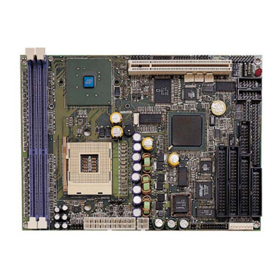
Page 14: Board Layout
Board Layout... -
Page 15: Jumper List
Jumper List Jumper Default Setting Setting Page Bus Clock Rate Select: Auto Detect Short 1-2 Clear CMOS: Normal Operation Short 1-2 Only for Debug ---- ---- Use RS-232 or RS-422/485 Select: Short 1-3, 2-4, RS-232 7-9, 8-10 Connector List Connector Definition Page MIC In/Audio Out Connector... -
Page 16: Configuring The Cpu
LTM10C348F), please contact with your sales. The onboard Intel 82845GE with 1MB or 8MB memory supporting CRT display up to 1280 x 1024 at 32-bit colors. The HS-4701 provides two connection methods of CRT and LVDS Panel device. CN10 offers an internal CRT connector, and J4, J5 offer two LVDS Panel connectors. -
Page 17: Pci E-Ide Drive Connector
CLK1P PCI E-IDE Drive Connector IDE1 and IDE2 are standard 40-pin connector daisy-chain driver connector serves the PCI E-IDE drive provisions onboard the HS-4701. A maximum of four ATA/33/66/100 IDE drives can connect to the HS-4701 via IDE1 and IDE2. - Page 18 IDE1: Primary IDE Connector Description Description IDERST# PDD7 PDD8 PDD6 PDD9 PDD5 PDD10 PDD4 PDD11 PDD3 PDD12 PDD2 PDD13 PDD1 PDD14 PDD0 PDD15 PDREQ PDIOW# PDIOR# PIORDY 470Ω Pull GND PDDACK# IRQ14 PDA1 P66DET PDA0 PDA2 PDCS#1 PDCS#3 IDEACTP#...
- Page 19 IDE2: Secondary IDE Connector Description Description IDERST# SDD7 SDD8 SDD6 SDD9 SDD5 SDD10 SDD4 SDD11 SDD3 SDD12 SDD2 SDD13 SDD1 SDD14 SDD0 SDD15 SDREQ SDIOW# SDIOR# SIORDY 470Ω Pull GND SDDACK# IRQ15 SDA1 S66DET SDA0 SDA2 SDCS#1 SDCS#3 IDEACTP#...
-
Page 20: Floppy Disk Drive Connector
Floppy Disk Drive Connector The HS-4701 uses a standard 34-pin header connector, FDC1, for floppy disk drive connection. A total of two FDD drives may be connected to FDC at any given time. FDC1: FDD Connector Description Description RWC# DS1#... -
Page 21: Serial Port Connectors
3.10 Serial Port Connectors The HS-4701 offers two NS16C550 compatible UARTs with Read/Receive 16-byte FIFO serial ports and four internal 10-pin headers. There is one RS-422/485 connector. CN11~CN14: COM1~COM4 Connectors (5x2 Header) PIN Description PIN Description DCD0 DSR0 RXDD0 RTS0... -
Page 22: Parallel Connector
RS-232 (default) Short 1-3, 2-4, 7-9, 8-10 RS-422/485 Short 3-5, 4-6, 9-11, 10-12 3.11 Parallel Connector LPT1 is a standard 26-pin flat cable connector deigned to accommodate parallel port connection onboard the HS-4701. LPT1: Parallel Connector Description Description STB# AFD#... -
Page 23: Ethernet Connector
RRX- ACTLED# LANC1 SPLED# LANC2 TTX+ TTX- 3.13 USB Connector The HS-4701 provides four USB ports, at locations USB1 and USB2, for four USB connections to the HS-4701. USB1: USB Connector PIN Description PIN Description USBP0N USBP1N USBP0P USBP1P USBP0N... -
Page 24: Cmos Data Clear
HS-4701 provides one 20-pin and one 4-pin ATX power connectors at PW1 and PW2. HS-4701 must using P4 power supply. One of 4-pin connector is for +12V lead which should connect to PW2. 20-pin ATX Power Connector can connect to Backplane or to PW1. -
Page 25: Keyboard/Mouse Connectors
Description MS_DATA MS_CLK KB_DATA KB_CLK 3.17 System Front Panel Connectors The HS-4701 has one LED at location CN3 that indicates the HDD status. CN3: HDD LED Connector Description 150Ω Pull +5V HDD ACTIVE# CN5 is the Reset Button connector onboard. The CN6 is Green... -
Page 26: External Speaker
150Ω Pull +5V ACTIVE# 3.18 External Speaker Aside from the buzzer at location BZ1 onboard, the HS-4701 also offers a connector (CN2) for an external speaker connection. The table below lists the pin assignments of CN2. CN2: External Speaker Connector... -
Page 27: Digital Input/Output
CD2: Line In Connector PIN Description PIN Description IN_R IN_L 3.20 Digital Input/Output The HS-4701 provides a CN7 connector for Digital I/O function. CN7: Digital I/O Connector PIN Description PIN Description VCC5 VCC5 DO_0 DI_0 DO_1 DI_1 DO_2 DI_2 DO_3... -
Page 28: Tv Out Function
3.21 TV Out Function HS-4701 can support TV-Out function which input could be up to 800 x 600 graphics resolutions. World Wide Video standards are supported including NTSC-M (North America, Taiwan), NTSC-J (Japan), PAL-B, D, G, H, I (Europe, Asia), PAL-M (Brazil), PAL-N (Uruguay, Paraguay) and PAL-NC (Argentina). -
Page 29: Chapter 4 Award Bios Setup
Chapter 4 Award BIOS Setup The HS-4701 uses Award BIOS for the system configuration. The Award BIOS setup program is designed to provide the maximum flexibility in configuring the system by offering various options that could be selected for end-user requirements. This chapter is written to assist you in the proper usage of these features. -
Page 30: Using Setup
Using Setup In general, you use the arrow keys to highlight items, press <Enter> to select, use the <PageUp> and <PageDown> keys to change entries, press <F1> for help and press <Esc> to quit. The following table provides more detail about how to navigate in the Setup program using the keyboard. -
Page 31: Main Menu
Main Menu Once you enter the Award BIOS CMOS Setup Utility, the Main Menu will appear on the screen. The Main Menu allows you to select from several setup functions and two exit choices. Use the arrow keys to select among the items and press <Enter> to enter the sub-menu. Phoenix –... -
Page 32: Standard Cmos Setup
Standard CMOS Setup The Standard Setup is used for the basic hardware system configuration. The main function is for Data/Time and Floppy/Hard Disk Drive settings. Please refer to the following screen for the setup. When the IDE hard disk drive you are using is larger than 528MB, you must set the HDD mode to LBA mode. -
Page 33: Advanced Cmos Setup
Advanced CMOS Setup This section allows you to configure your system for the basic operation. You have the opportunity to select the system’s default speed, boot-up sequence, keyboard operation, shadowing and security. Phoenix – AwardBIOS CMOS Setup Utility Advanced BIOS Features Item Help Virus Warning [Disabled]... -
Page 34: Advanced Chipset Setup
Advanced Chipset Setup This section allows you to configure the system based on the specific features of the installed chipset. This chipset manages bus speeds and the access to the system memory resources, such as DRAM and the external cache. It also coordinates the communications between the conventional ISA and PCI buses. -
Page 35: Power Management Setup
Power Management Setup The Power Management Setup allows user to configure the system for saving energy in a most effective way while operating in a manner consistent with his own style of computer use. Phoenix – AwardBIOS CMOS Setup Utility Power Management Setup ACPI function [Enabled]... -
Page 36: Pci / Plug And Play Setup
PCI / Plug and Play Setup This section describes configuring the PCI bus system. PCI, or Personal Computer Interconnect, is a system that allows I/O devices to operate at speeds nearing the speed the CPU itself uses when communicating with its own special components. This section covers some very technical items and it is strongly recommended that only experienced users should make any changes to the default settings. -
Page 37: Peripheral Setup
Peripheral Setup The IDE hard drive controllers can support up to four separate hard drives. These drives have a master/slave relationship that is determined by the cabling configuration used to attach them to the controller. Your system supports two IDE controllers--a primary and a secondary--so you can install up to four separate hard disks. -
Page 38: Pc Health Status
4.10 PC Health Status Phoenix – AwardBIOS CMOS Setup Utility PC Health Status CPU Warning Temperature [Disabled] Item Help Current System Temp. Menu Level Current CPU1 Temperature Current CPUFAN1 Speed Current CPUFAN2 Speed Current CPUFAN3 Speed IN0(V) IN1(V) IN2(V) +12V -12V VBAT(V) 5VSB(V) -
Page 39: Chapter 5 Software Utilities
5.1.1 Installing Intel Chipset Software Utility Insert Utility CD Disk to your CD ROM drive. The main menu will pop up as shown below. Select on the HS-4701 button to launch the installation program. Click on the ICH4 Driver button to continue. - Page 40 Immediately after clicking the IDE button in Step 1, the program launches the InstallShield Wizard that will assist you in the installation process. Click on the Next > button to proceed. The Intel OEM Software License Agreement dialog box then appears on the screen.
- Page 41 When the Readme Information dialog box pops up, just click on the Next button to proceed. Once the Install Shield Wizard finishes updating your system, it will prompt you to restart the computer. Tick on the Yes, I want to restart my computer now followed by a click on the Finish button to reboot.
- Page 42 5.1.2 Installing Intel Application Accelerator Insert Utility CD Disk to your CD ROM drive. The main menu will pop up as shown below. Select on the HS-4701 button to launch the installation program. Click on the IDE Driver button to continue.
- Page 43 The Intel OEM Software License Agreement dialog box then appears on the screen. Choose Yes to proceed. Setup will then prompt you to specify the path where you would like the Security driver installed. Select the Next > button after you have made your path/installation choice.
-
Page 44: Vga Driver Installation
VGA Driver Installation 5.2.1 Win 98 Insert Utility CD Disk to your CD ROM drive. The main menu will pop up as shown below. Select on the HS-4701 button to launch the installation program. Click on the VGA Driver button to continue. - Page 45 Click on the Windows 9x button to continue. When the dialog box below appears, make sure you close all other Windows applications then click on the Next > button to proceed. The Intel OEM Software License Agreement dialog box then appears on the screen.
- Page 46 Once the setup program finishes copying files into your system, it will prompt you to restart the computer. Tick on the Yes, I want to restart my computer now followed by a click on the Finish button to reboot. Only after your computer boots will the new settings take effect.
- Page 47 Please make sure you have already install Service Pack 6.0. Insert Utility CD Disk to your CD ROM drive. The main menu will pop up as shown below. Select on the HS-4701 button to launch the installation program. Click on the VGA Driver button to continue.
- Page 48 When the dialog box below appears, make sure you close all other Windows applications then click on the Next > button to proceed. The Intel OEM Software License Agreement dialog box then appears on the screen. Choose Yes to proceed.
- Page 49 5.2.3 Win 2000 Insert Utility CD Disk to your CD ROM drive. The main menu will pop up as shown below. Select on the HS-4701 button to launch the installation program. Click on the VGA Driver button to continue.
- Page 50 Click on the Windows 2K button to continue. When the dialog box below appears, make sure you close all other Windows applications then click on the Next > button to proceed.
- Page 51 The Intel OEM Software License Agreement dialog box then appears on the screen. Choose Yes to proceed. Once the setup program finishes copying files into your system, it will prompt you to restart the computer. Tick on the Yes, I want to restart my computer now followed by a click on the Finish button to reboot.
-
Page 52: Lan Driver Installation
LAN Driver Installation 5.3.1 Win 95/98 Insert Utility CD Disk to your CD ROM drive. The main menu will pop up as shown below. Select on the HS-4701 button to launch the installation program. Click on the LAN Driver button to continue. - Page 53 When the dialog box below appears, make sure you close all other Windows applications then click on the Next > button to proceed. The Intel OEM Software License Agreement dialog box then appears on the screen. Choose Accept to proceed.
- Page 54 The Setup Type dialog box then appears on the screen. Choose Typical to proceed. When the dialog box below appears, make sure you close all other Windows applications then click on the Install button to proceed.
- Page 55 When the dialog box below appears, it means your driver is install completed. Click Finish button to proceed. Once the setup program finishes copying files into your system, it will prompt you to restart the computer. Tick on the Yes to reboot.
- Page 56 Tick on the Wired to Network once the following screen appears. Click on the Next to proceed. Click on the Start Search button for the program to locate the Network Adapter.
- Page 57 Once setup finishes the search, it will list a number of adapters for you to choose from. Press on the Have Disk button to assign the driver path location. Setup now asks you for the location of the driver. When you have entered the new driver path, press on the OK button to continue.
- Page 58 Setup then returns to Network Setup Wizard screen and displays your new Network Adapter. Click on Next to continue. The Network Setup Wizard then allows you to set the Network Protocols on your network. Select the appropriate protocol and then click on Next to continue.
- Page 59 Before Setup starts installing the components found and the settings you made, it will give you the option to proceed or go back for changes from the following screen. Click on the Next button once you are sure of your devices. 10.
- Page 60 13. When the screen below appears, click on Next to continue. 14. Setup then prompts you that it is ready to start the network. You may complete the installation thereafter. Click on Next to continue.
-
Page 61: Audio Driver Installation
16. Click on the Yes button to restart your computer. The LAN driver installation for WIN NT4.0 is now complete. Audio Driver Installation Insert Utility CD Disk to your CD ROM drive. The main menu will pop up as shown below. Select on the HS-4701 button to launch the installation program. - Page 62 Click on the AUDIO Driver button to continue. When the dialog box below appears, make sure you close all other Windows applications then click on the Next > button to proceed.
- Page 63 Once the InstallShield Wizard completes the operation and update of your AC97 driver, it will ask you to remove disks from their drives, and prompt you to restart your system. Tick on the Yes, I want to restart my computer now. Afterwards, click on the Finish button to complete the installation process.
- Page 64 This page intentionally left blank.
Need help?
Do you have a question about the HS-4701 and is the answer not in the manual?
Questions and answers