
Related Manuals for Boser HS-2606


Summary of Contents for Boser HS-2606
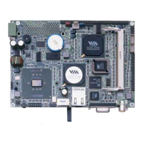
- Page 1 HS-2606 ULV Intel® Celeron® processor Embedded Engine Board •CompactFlash•PCMCIA•Mini PCI• •CRT/Panel•TV-Out•LAN•Audio• •ATA/33/66/100•4 COM•USB2.0•WDT•...
- Page 2 Unauthorized reproduction, transmission, translation, and storage of any form and means (i.e., electronic, mechanical, photocopying, recording) of this document, in whole or partly, is prohibited, unless granted permission by BOSER Technology Co., Ltd. reserves the right to change or improve the contents of BOSER Technology Co., Ltd.
-
Page 3: Table Of Contents
Table of Contents Chapter 1 General Description ........1 1.1 Major Features ............... 2 1.2 Specifications ................ 3 1.3 Board Dimensions..............4 Chapter 2 Unpacking ..........5 2.1 Opening the Delivery Package..........5 2.2 Inspection................5 Chapter 3 Hardware Installation ......7 3.1 Before Installation ..............7 3.2 Board Layout ................. - Page 4 Chapter 4 AMI BIOS Setup ........21 4.1 Starting Setup..............21 4.2 Using Setup ................. 22 4.3 Main Menu................23 4.4 Standard CMOS Setup ............24 4.5 Advanced CMOS Setup ............25 4.6 Advanced Chipset Setup............ 26 4.7 Power Management Setup ..........27 4.8 PCI / Plug and Play Setup...........
- Page 5 Safety Instructions Integrated circuits on computer boards are sensitive to static electricity. To avoid damaging chips from electrostatic discharge, observe the following precautions: Do not remove boards or integrated circuits from their anti-static packaging until you are ready to install them. Before handling a board or integrated circuit, touch an unpainted portion of the system unit chassis for a few seconds.
-
Page 7: Chapter 1 General Description
CRT/Panel, audio, LAN TV-Out, 4 COM, and USB2.0 interfaces. Its onboard ATA/33/66/100 to IDE drive interface architecture allows the HS-2606 to supports data transfers of 33, 66 or 100MB/sec. To one IDE drive connection. Designed with the VIA CLE266/VT8235 core logic chipset, the board supports VIA Eden 1GHz Embedded CPU. -
Page 8: Major Features
Additional onboard connectors include 4 USB2.0 port providing faster data transmission. And one external RJ-45 connector for 10/100 Based Ethernet use. Major Features The HS-2606 comes with the following features: ULV Intel® Celeron® embedded 400/650MHz One SO-DDR socket with a max. capacity of 1GB VIA CLE266/VT8235 chipset... -
Page 9: Specifications
Specifications CPU: ULV Intel® Celeron® processor 400/650MHz Memory: One SO-DDR socket supports up to 1GB Chipset: VIA CLE266/VT8235 I/O Chipset: Winbond W83697UF CompactFlash: One, Type I/II IDE interface adapter PCMCIA: Two PC Card or CardBus slots PCI Slot: One, Type I mini PCI slot VGA: VIA CLE266 integrated S3 3D supports AGP Bus and Hardware MPEG-2 TV-Out: Supports PAL or NTSC TV system... -
Page 10: Board Dimensions
Board Dimensions... -
Page 11: Chapter 2 Unpacking
Chapter 2 Unpacking Opening the Delivery Package The HS-2606 is packed in an anti-static bag. The board has components that are easily damaged by static electricity. Do not remove the anti-static wrapping until proper precautions have been taken. Saftey instructions in front of this manual describe anti-static precautions and procedures. - Page 12 Cables Package Description 4-pin power cable x 1 MIC/Audio cable x 1 8-pin USB split type cable x 1 PS/2 KB/MS transfer cable x 1 RS-232 cable x 4 IDE flat cable x 1 It is recommended that you keep all the parts of the delivery package intact and store them in a safe/dry place for any unforeseen event requiring the return shipment of the product.
-
Page 13: Chapter 3 Hardware Installation
Chapter 3 Hardware Installation This chapter provides the information on how to install the hardware using the HS-2606. This chapter also contains information related to jumper settings of switch, and watchdog timer selection etc. Before Installation After confirming your package contents, you are now ready to install your hardware. -
Page 14: Board Layout
Board Layout... -
Page 15: Jumper List
MIC In/Audio Out Connector LCD1 44-pin Panel Connector PCMCIA Connector Mini PCI Connector Configuring the CPU The HS-2606 v2.0 embedded with a ULV Intel® Celeron® processor 400/650MHz. User don’t need to adjust the frequently and check speed of Intel® processor. -
Page 16: System Memory
Before you turn on the power of your system, please set JBAT1 to Short 1-2 for normal operation. Power and Fan Connectors HS-2606 provides one 4-pin power connector at CN1. And one 2-pin ATX power in at CN3. +10~+30V wide range single DC power in can make HS-2606 suitable for all kinds of environments even more. -
Page 17: System Front Panel Control
CN3: 2-pin ATX Power In Control PIN Description PS_ON 5VSB CN4: External Reset Button Description RST_SW FN1: Fan Power In Connector Description System Front Panel Control J2: System Front Panel Control PIN Description Description 330Ω Pull +5V Speaker HDD LED PW Button 330Ω... -
Page 18: Vga Controller
3.10 VGA Controller The HS-2606 provides two connection methods of a VGA device. CN7 offers a single standard CRT connector while LCD1 is the 44-pin panel connector. VIA CLE266 VGA chipset shared main memory 8/16/32MB, and provides high quality DVD video playback. HS-2606 also provides Hardware MPEG-2. - Page 19 Please set the proper voltage of your panel use JP2 before proceeding on installing it. The HS-2606 has an onboard jumper that selects the working voltage of the flat panel connected to the system. Jumper JP2 offers two voltages setting for the user.
-
Page 20: Tv-Out Connector
3.11 TV-Out Connector The HS-2606 can supports TV-Out function which input could be up to 800 x 600 graphics resolutions. World Wide Video standards are supported including NTSC-M (North America, Taiwan), NTSC-J (Japan), PAL-B, D, G, H, I (Europe Asia), PAL-M (Brazil), PAL-N (Uruguay, Paraguay) and PAL-NC (Argentina). -
Page 21: Audio Connectors
3.13 Audio Connectors The HS-2606 has an onboard AC97 3D audio controller. The following tables list the pin assignments of the Line In/Audio Out connector. JP1: MIC In/Audio Out Connector PIN Description PIN Description AOUTL AOUTR MIC IN J1: Line In Connector... -
Page 22: Pci E-Ide Drive Connector
3.14 PCI E-IDE Drive Connector CN13 is a standard 44-pin 2.0-pitch connector daisy-chain driver connector serves the PCI E-IDE drive provisions onboard the HS-2606. A maximum of two ATA/33/66/100 IDE drives can be connected to the HS-2606 via CN11. CN13: IDE Connector... -
Page 23: Serial Port Connectors
Receive 16-byte FIFO serial ports and internal 10-pin headers. CN8/CN9/CN12/CN11: COM 1~COM 4 Connector (5x2 Header) PIN Description PIN Description 3.16 USB Connector The HS-2606 provides two 8-pin connectors, at location J4 and J5, for four USB2.0 ports to the HS-2606. J5/J6: USB2.0 Connector Description Description... -
Page 24: Keyboard/Mouse Connectors
3.17 Keyboard/Mouse Connectors The HS-2606 offers two possibilities for keyboard/mouse connections. The connections are via CN3 for an external PS/2 type keyboard/mouse OR CN13 for 6-pin header. CN5: PS/2 6-pin Mini DIN KB/MS Connector Description Keyboard Data Mouse Data Keyboard Clock Mouse Clock 3.18 Watchdog Timer... -
Page 25: Gpio Function
01 Time-out occurs after 1 second/minute 02 Time-out occurs after 2 second/minute ff Time-out occurs after 255 second/minute 3.19 GPIO Function The HS-2606 offers four general purpose I/O ports with the following capabilities: I2C/SMB Support Thermal Detect Notebook Lid Open/close Detect... -
Page 26: Mini Pci Slot
3.21 CompactFlash Connector The HS-2606 also offers a Type I/II CompactFlash connector which is IDE interface located at the solder side of the board (beneath the SO-DIMM connector). The designated CN14 connector, once soldered with an adapter, can hold CompactFlash... -
Page 27: Chapter 4 Ami Bios Setup
Chapter 4 AMI BIOS Setup The HS-2606 uses AMI BIOS for the system configuration. The AMI BIOS setup program is designed to provide the maximum flexibility in configuring the system by offering various options that could be selected for end-user requirements. This chapter is written to assist you in the proper usage of these features. -
Page 28: Using Setup
Using Setup In general, you use the arrow keys to highlight items, press <Enter> to select, use the <PageUp> and <PageDown> keys to change entries, and press <Esc> to quit. The following table provides more detail about how to navigate in the Setup program using the keyboard. Move to previous item ↑... -
Page 29: Main Menu
Main Menu Once you enter the AMI BIOS CMOS Setup Utility, the Main Menu will appear on the screen. The Main Menu allows you to select from several setup functions and two exit choices. Use the arrow keys to select among the items and press <Enter>... -
Page 30: Standard Cmos Setup
Standard CMOS Setup The Standard Setup is used for the basic hardware system configuration. The main function is for Data/Time and Floppy/Hard Disk Drive settings. Please refer to the following screen for the setup. When the capacity of the IDE hard disk drive is larger than 528MB, you must set the HDD mode to LBA mode. -
Page 31: Advanced Cmos Setup
Advanced CMOS Setup This section allows you to configure your system for the basic operation. You have the opportunity to select the system’s default speed, boot-up sequence, keyboard operation, shadowing and security. AMIBIOS SETUP – ADVANCED CMOS SETUP (C)2001 American Megatrends, Inc. All Rights Reserved Quick Boot Enabled Available Options:... -
Page 32: Advanced Chipset Setup
Advanced Chipset Setup This section allows you to configure the system based on the specific features of the installed chipset. This chipset manages bus speeds and the access to the system memory resources, such as DRAM and the external cache. It also coordinates the communications between the conventional ISA and PCI buses. -
Page 33: Power Management Setup
Power Management Setup AMIBIOS SETUP – PCI / PLUG AND PLAY SETUP (C)2001 American Megatrends, Inc. All Rights Reserved ACPI Aware O/S Available Options: ACPI Standby State S1/POS USB Device Wakeup Function Enabled Re-Call VGA BIOS at S3 Resuming Enabled Power Management / APM Enabled Video Power Down Mode... -
Page 34: Pci / Plug And Play Setup
PCI / Plug and Play Setup This section describes configuring the PCI bus system. PCI, or Personal Computer Interconnect, is a system that allows I/O devices to operate at speeds nearing the speed the CPU itself uses when communicating with its own special components. This section covers some very technical items and it is strongly recommended that only experienced users should make any changes to the default settings. -
Page 35: Peripheral Setup
Peripheral Setup The IDE hard drive controllers can support up to two separate hard drives. These drives have a master/slave relationship that is determined by the cabling configuration used to attach them to the controller. Your system supports two IDE controllers--a primary and a secondary--so you can install up to four separate hard disks. -
Page 36: Auto-Detect Hard Disks
4.10 Auto-Detect Hard Disks This option detects the parameters of an IDE hard disk drive, and automatically enters them into the Standard CMOS Setup screen. Up to four IDE drives can be detected, with parameters for each appearing in sequence inside a box. To accept the displayed entries, press the “Y”... -
Page 37: Change Supervisor/User Password
4.11 Change Supervisor/User Password AMIBIOS HIFLEX SETUP UTILITY – VERSION x.xx (C)2001 American Megatrends, Inc. All Rights Reserved Standard CMOS Setup Advanced CMOS Setup Advanced Chipset Setup Power Management Setup Enter new supervisor password: _ Change Supervisor Password Auto Configuration with Optimal Settings Auto Configuration with Fail Safe Settings Save Settings and Exit Exit Without Saving... -
Page 38: Auto Configuration With Optimal Settings
PASSWORD DISABLED. When a password has been enabled, you will be prompted to enter it every time you try to enter Setup. This prevents an unauthorized person from changing any part of your system configuration. Additionally, when a password is enabled, you can also require the BIOS to request a password every time your system is rebooted. -
Page 39: Auto Configuration With Fail Safe Settings
4.13 Auto Configuration with Fail Safe Settings When you press <Enter> on this item you get a confirmation dialog box with a message similar to the figure below. This option allows you to load/restore the default values to your system configuration, optimizing and enabling all high performance features. -
Page 40: Save Settings And Exit
4.14 Save Settings and Exit Pressing <Enter> on this item asks for confirmation: AMIBIOS HIFLEX SETUP UTILITY – VERSION x.xx (C)2001 American Megatrends, Inc. All Rights Reserved Standard CMOS Setup Advanced CMOS Setup Advanced Chipset Setup Power Management Setup Save current settings and exit (Y/N) ? Y Change Supervisor Password Auto Configuration with Optimal Settings Auto Configuration with Fail Safe Settings... -
Page 41: Exit Without Saving
4.15 Exit Without Saving Pressing <Enter> on this item asks for confirmation: Quit without saving (Y/N)? Y This allows you to exit Setup without storing in CMOS any change. The previous selections remain in effect. This exits the Setup utility and restarts your computer. - Page 42 This page is the blank page.
-
Page 43: Chapter 5 Software Utilities
Chapter 5 Software Utilities The chapter contains the detailed information of VGA, LAN, audio, and USB2.0 driver installation procedures. The drivers are located in the following directories of the utility disk: VGA Driver: \VGA\WIN98_ME or \VGA\XP_2K LAN Driver: \LAN Audio Driver: \AC97 USB2.0 Driver: \USB20\2K or \USB\XP VGA Driver Installation 5.1.1 WIN95/98... - Page 44 Select the operation system of your computer to proceed with the installation process. Click on the “Setup.exe” and to go setup.
- Page 45 Once the Welcome screen appears on the screen, make sure to close applications that are running and then click the Next> button. When the display below appears on your screen, Setup is already ready to install and copy the related files onto your hard drive.
- Page 46 After the installation finishes, you will be prompted to restart your system. We recommend you to reboot your computer to allow the new settings to take effect. Click on the Finish button to reboot. 5.1.2 VGA Driver Installation for WIN2K/XP NOTE: Please make sure you have already installed Service Pack 6.0.
- Page 47 Select the operating system of your computer to proceed with the installation process. Click on the “Setup.exe” and to go setup.
- Page 48 Once the Welcome screen appears on the screen, make sure to close applications that are running and then click the Next button. When the display below appears on your screen, Setup is already ready to install and copy the related files onto your hard drive. Click on the Next button to proceed.
- Page 49 After the installation finishes, you will be prompted to restart your system. We recommend you to reboot your computer to allow the new settings to take effect. Click on the Finish button to reboot. 5.1.3 VGA Driver Installation for WIN NT4.0 Click the Start button on the lower left hand corner of your screen, then select Setting.
- Page 50 Click on the Settings tab, and then choose Display Type. In the Change Display Type window, click on Have Disk.
- Page 51 Specify the path of the new driver and then press on Enter. (If in driver E:, type E:\Vga\WinNT) Select VIA/S3G UniChrome Graphics, then click OK or press Enter.
- Page 52 You will see warning panel about Third Party Drivers. Click on Yes to finish the installation. Once the installation is completed, you must shut down the system and restart for the new driver to take effect.
-
Page 53: Lan Driver Installation
Press on the OK button as soon as you have located the path of your driver. LAN Driver Installation 5.2.1 LAN Driver Installation for WIN95/98/2K With the Utility CD Disk still in your CD ROM drive, right click on My Computer icon from the Windows menu. - Page 54 Select on PCI Ethernet Controller from Other devices list, right-click and then select on Properties. The PCI Ethernet Controller Properties screen then appears, allowing you to reinstall the driver. Select Driver from the main menu to proceed.
- Page 55 Browse button to manually specify the path. (If in E:, type E:\HS-2606 Driver\LAN\/w/in98) Update Device Driver Wizard will ask are you sure to updated driver, tick on update, and then press Next to continue.
- Page 56 Once the program detects the device driver (*.inf) file from your specified location, it will automatically copy the files into your hard drive. The program then copies the necessary files from your Windows installation disk to complete the driver setup process. Once the driver is completely installed, the following message appears on your display.
- Page 57 Restart your computer to make the new system settings take effect. Click on the Yes button when the screen below appears and your LAN Driver for Win95 and Win98 are now completely installed. 5.2.2 LAN Driver Installation for WIN NT4.0 With the Utility CD Disk still in your CD ROM drive, right click on Network Neighborhood icon from the Windows menu.
- Page 58 Tick on the “Wired to Network” once the following screen appears. Click on the Next to proceed. Click on the Start Search button for the program to locate the Network Adapter.
- Page 59 Once setup finishes the search, it will list a number of adapters for you to choose from. Press on the Have Disk button to assign the driver path location. Setup now asks you for the location of the driver. When you have entered the new driver path, press on the OK button to continue.
- Page 60 Setup then returns to Network Setup Wizard screen and displays your new Network Adapter. Click on Next to continue. The Network Setup Wizard then allows you to set the Network Protocols on your network. Select the appropriate protocol and then click on Next to continue.
- Page 61 The Network Setup Wizard then allows you to set the Network Services on your Network, then click on Next to continue. Before Setup starts installing the components found and the settings you made, it will give you the option to proceed or go back for changes from the following screen.
- Page 62 Windows NT Setup will then need to copy files necessary to update the system information. Specify the path then press Continue. Once it finishes copying the files, Setup will now allow you to choose the Duplex Mode of your LAN controller. Press on the Continue button after making your selection.
-
Page 63: Audio Driver Installation
Restart your computer. The LAN driver installation for WIN NT4.0 is now complete. Audio Driver Installation 5.3.1 Audio Driver Installation for WIN98/2K/XP With the Utility CD Disk still in your CD ROM drive, open the File Manager and then select the driver folder. (If in E:, type E:\HS-2606 Driver\AC97) - Page 64 Press “Setup.exe” and to go setup. Once the Welcome screen appears on the screen, make sure to close applications that are running and then click the Next button.
- Page 65 The Select Components dialog box is now displayed. Select on Install driver and then click on Next. After the audio driver installation finishes, select the Finish button to complete the installation process.
- Page 66 5.3.2 Audio Driver Installation for WINNT With the Utility CD Disk still in your CD ROM drive, open the File Manager and then select the driver folder. (If in E:, type E:\HS-2606 Driver\AC97) Press “Setup.exe” and to go setup.
- Page 67 Once the Welcome screen appears on the screen, make sure to close applications that are running and then click the Next button. The Select Components dialog box is now displayed. Select on VT8233/VT8235 and then click on Next.
- Page 68 After the audio driver installation finishes, select restart computer now, and click the Finish button to complete the installation process.
-
Page 69: Usb2.0 Driver Installation
USB2.0 Driver Installation 5.4.1 Win 98 With the Utility CD Disk still in your CD ROM drive, right click on “My Computer” icon from the Windows menu. Select on System Properties and then proceed to the Device Manager from the main menu. - Page 70 The PCI Universal Serial Bus Properties screen then appears, allowing you to re-install the driver. Select Driver from the main menu to proceed. When the dialog box below appears, make sure you close all other Windows applications then click on the Next > button to proceed.
- Page 71 Tick on the “Search for a better driver” once the following screen appears. Click on the Next to proceed. Once the program returns to the Add New Hardware Wizard screen, your specified location will appear. Press on the Next button to continue.
- Page 72 When Setup finds the information it needs about the new driver, it will display the device it found on the following screen. Press on the Next button to accept and proceed. Once the InstallShield Wizard completes the operation and update of your USB2.0 driver.
- Page 73 5.4.2 Win 2000 With the Utility CD Disk still in your CD ROM drive, right click on “My Computer” icon from the Windows menu. Select on System Properties and then proceed to the Device Manager from the main menu. Select on Other Devices from the list of devices then double-click on PCI Universal Serial Bus.
- Page 74 When the dialog box below appears, make sure you close all other Windows applications then click on the Next > button to proceed. Tick on the “Search for a suitable driver” once the following screen appears. Click on the Next to proceed.
- Page 75 Once the program returns to the Add New Hardware Wizard screen, your specified location will appear. Press on the Next button to continue. Choose sisusb2.inf and press on the Open button to accept and proceed.
- Page 76 USB2.0 driver. Click on the Finish button to complete the installation process. 5.4.3 Win XP With the Utility CD Disk still in your CD ROM drive, open the File Manager and then select the driver folder. (If in E:, type E:\HS-2606 Driver\USB2.0)
- Page 77 Click on “Setup.exe” and to go setup. When the dialog box below appears, make sure you close all other Windows applications then click on the Next > button to proceed.
- Page 78 The programs starts to install the USB2.0 driver when you click the Next> button on the screen below. Once the InstallShield Wizard completes the operation and update of your USB2.0 driver. Click on the Yes button to restart computer to complete the installation process.
Need help?
Do you have a question about the HS-2606 and is the answer not in the manual?
Questions and answers