
Subscribe to Our Youtube Channel
Related Manuals for OHIOSTEEL AllFitHD AF-5026LS


Summary of Contents for OHIOSTEEL AllFitHD AF-5026LS
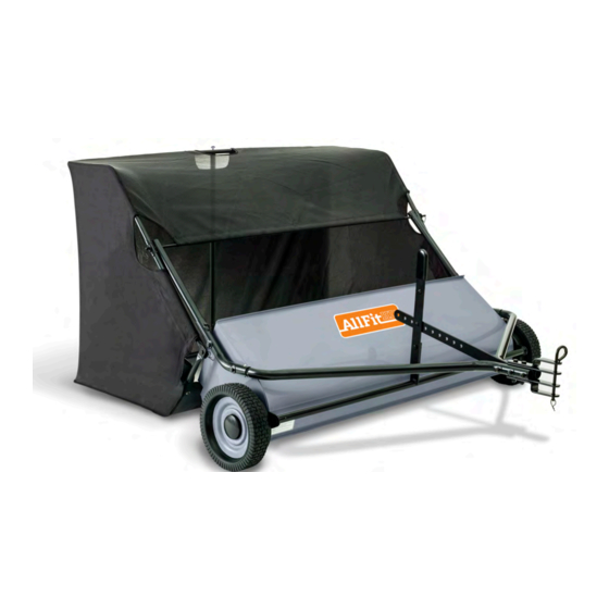
- Page 1 AF-5026LS 26 cu. ft. LAWN SWEEPER READ AND FOLLOW ALL SAFETY RULES AND OPERATING INSTRUCTIONS BEFORE USING THIS EQUIPMENT 6000680 - REV C 9/19...
-
Page 2: Safety Rules
Safety Rules This is the safety alert symbol. It is used to alert you to potential personal injury hazards. Obey all safety messages that follow this symbol to avoid possible injury or death. Read and understand all safety rules and operating instructions before using this tractor attachment. -
Page 3: Warranty
Paint that is worn or faded due to normal use or exposure. To arrange for product repair visit ohiosteel.com/customer-support and fill out the warranty repair form. You can also call 1-800-652-2321, ext. 212 to speak to our Customer Service Team This warranty gives you specific legal rights, and you may also have other rights which may vary from state to state. -
Page 4: Carton Contents
Carton Contents 3 (x1) 4 (x1) 5 (x2) (x1) 6 (x2) 18 (x2) 19 (x2) 20 (x4) 22 (x11) 21 (x10) 23 (x2) 24 (x2) 26 & 48 (x8) 27 (x4) 25 (x3) 36 (x2) 37 (x1) 39 (x2) 38 (x2) 40 (x2) 41 (x1) 42 (x1) - Page 5 Assembly Instructions Attach Hitch Mount Tubes (19) to Sweeper Assembly and tighten hardware. DO NOT OVERTIGHTEN. Attach Handle (3) to Height Adjustment (2) and tighten hardware. Insert Hitch Tubes (18) into Hitch Mount Tubes (19) and snap into position.
- Page 6 Assembly Instructions Install hardware through front two holes of Hitch Tubes as shown. DO NOT TIGHTEN AT THIS TIME. Hold Adjustment Lever (4) in position and install third bolt through Lever as shown. Pin Adjustment Lever to Handle with Hair Pin (26). SHOWN INSTALLED DO NOT TIGHTEN AT THIS TIME.
- Page 7 Assembly Instructions Install Clevis Bars as shown (5 & 6); Clevis bolts (23) pass between Hitch Tube bolts. Tighten Hitch Tube hardware first, then tighten Clevis hardware. Insert Bottom Frame Tubes (38) into Center Frame Tube (40) and snap into position. (Note that snap buttons are oriented up) Snap Button...
- Page 8 Assembly Instructions Unroll and flatten hopper bag (37) from shipping state. Then, slide Hopper Stop Bar (43) into pocket of Hopper Bag as shown. First, place bottom frame assembly into bottom of Hopper Bag (37). Second, Install Clevis Pins (45) through Hopper Bag (37), Hopper Stop Bar (41), and Bottom Frame Tubes (38) then secure with Hairpins(48).
- Page 9 Assembly Instructions First, Place top frame assembly into Hopper Bag (37). Second, Install Clevis Pins (44) through Top Frame Tubes (39) and Bottom Frame Tubes (38) and secure with Hairpins (48). Snap Button Down Slide Hopper Pivot Rod (42) through Top Frame Tube (39) and Connecting Tube (36), then through pocket of Hopper Bag (37), and then through both Connecting Tube (36) and Top Frame Tube (39) on other side.
- Page 10 Assembly Instructions First, unscrew Thumb Screw from Tension Tube Assembly (41). Next, Hold Hopper Bag (37) open and carefully insert Tension Tube Assembly (41) through opening in Hopper Bag and into hole in bottom Center Frame Tube (40). Pull top Center Frame Tube over tension tube and align holes.
- Page 11 Assembly Instructions Insert Connecting Tubes (36) into Hitch Mount Tubes (19) and secure with Quick-Release Pins (47). Install Hitch Pin (49) and secure with Hairpin (48). Tie Dump Rope (51) securely around exposed section of Center Frame Tube (40). Do NOT fasten rope to any part of your body or clothing.
- Page 12 Operating Instructions Before Using Lawn Sweeper: Read all Safety Rules found on page 1. How to Sweep Lawn: Remove large debris from lawn. Do not sweep if conditions are too wet or muddy. Attach Lawn Sweeper to tractor using supplied hitch pin. The multi-pronged hitch allows the Lawn Sweeper to accomodate varying tractor hitch heights;...
- Page 13 Operating Instructions Storing Lawn Sweeper: Empty hopper bag and thoroughly clean Lawn Sweeper before storing. Store Lawn Sweeper away from excessive heat to prevent damage. Brushes must not contact ground during storage to prevent damage. Remove quick-release pins to separate hopper bag from Lawn Sweeper. Carefully remove tension tube and collapse hopper bag for compact storage.
-
Page 14: Repair Parts
14 3000721-ZC WASHER, 3/4" SAE PINION ASSEMBLY, LEFT 6000828 15 3000539-ZC 1/4" -20 X 1-1/4" BOLT BEARING ASSEMBLY 16 3000716-ZC WASHER, 1/4" SAE 6000540 WHEEL BUSHING 300065-ZC 1/4" -20 LOCK NUT 6000222-ZC SNAP BUTTON 307038-B2 TUBE, HITCH ohiosteel.com/partstore OHIO STEEL INDUSTRIES1-800-652-2321... - Page 15 BOTTOM FRAME TUBE 3/8" USS FLAT WASHER TOP FRAME TUBE QUICK-RELEASE PIN 307133 6004134-B2 CENTER FRAME TUBE HAIRPIN TENSION TUBE ASSEMBLY HITCH PIN 307053-B2 HOPPER PIVOT ROD 6000208-ZC SNAP BUTTON 307062-B2 HOPPER STOP BAR 307361 DUMP ROPE ohiosteel.com/partstore OHIO STEEL INDUSTRIES1-800-652-2321...
- Page 16 DESIGNED AND TESTED IN COLUMBUS, OHIO MANUFACTURED IN THE U.S.A. FROM DOMESTIC AND IMPORTED COMPONENTS MODEL # AF-5026LS (800) 652-2321...
- Page 17 AF-5026LS BARREDORA DE CÉSPED de 26 pies cúbicos LEA Y SIGA TODAS LAS REGLAS DE SEGURIDAD E INSTRUCCIONES DE USO ANTES DE UTILIZAR ESTE EQUIPO 6000680 - REV C 9/19...
-
Page 18: Reglas De Seguridad
Reglas de seguridad Este es el símbolo de alerta de seguridad. Se usa para alertarlo sobre posibles peligros de lesiones. Obedezca todos los mensajes de seguridad que aparezcan después de este símbolo para evitar posibles lesiones o la muerte. Lea y entienda todas las reglas de seguridad e instrucciones de uso antes de utilizar este accesorio para el tractor. - Page 19 • Pintura desgastada o descolorida debido al uso normal o a la exposición. Para programar la reparación del producto visite ohiosteel.com/customer-support y llene el formulario de garantía de reparación. También puede llamar al 1-800-652-2321, ext. 212 para hablar con nuestro Equipo de Servicio al Cliente.
- Page 20 Carton Contents 3 (x1) 4 (x1) 5 (x2) (x1) 6 (x2) 18 (x2) 19 (x2) 20 (x4) 22 (x11) 21 (x10) 23 (x2) 24 (x2) 26 & 48 (x8) 27 (x4) 25 (x3) 36 (x2) 37 (x1) 39 (x2) 38 (x2) 40 (x2) 41 (x1) 42 (x1)
-
Page 21: Instrucciones De Ensamblado
Instrucciones de ensamblado Conecte los tubos de montaje de enganche (19) al conjunto de la barredora y apriete los herrajes. NO APRIETE EN EXCESO. Conecte la manija (3) para ajustar la altura (2) y apriete los herrajes. Inserte los tubos de enganche (18) en los tubos de montaje de enganche (19) y ajústelos en su posición. - Page 22 Instrucciones de ensamblado Instale los herrajes a través de los dos orificios frontales de los tubos de enganche, tal como se muestra. NO LOS APRIETE AÚN. Sostenga la palanca de ajuste (4) en posición y coloque el tercer tornillo a través de la palanca, tal como se muestra.
- Page 23 Instrucciones de ensamblado Instale las barras de la horquilla tal como se muestra (5 y 6); los tornillos de la horquilla (23) se pasan entre los tornillos del tubo de enganche. Apriete primero los herrajes del tubo de enganche y luego los herrajes de la horquilla. Inserte los tubos del bastidor inferior (38) en el tubo del bastidor central (40) y ajústelo en su posición (asegúrese que los botones de presión estén hacia arriba).
- Page 24 Instrucciones de ensamblado Tome la bolsa de depósito (37) tal como viene y desenróllela y aplánela. Luego, deslice la barra de detención del depósito (43) dentro del bolsillo de la bolsa, tal como se muestra. Primero, coloque la estructura del bastidor inferior en el fondo de la bolsa de depósito (37). Segundo, coloque los pasadores de horquilla (45) a través de la bolsa de depósito (37), la barra de detención del depósito (41) y los tubos del bastidor inferior (38), y luego asegúrelos con horquillas (48).
- Page 25 Instrucciones de ensamblado Primero, coloque la estructura del bastidor superior en la bolsa de depósito (37). Segundo, coloque los pasadores de horquilla (44) a través de los tubos del bastidor superior (39) y los tubos del bastidor inferior (38) y asegúrelos con horquillas (48). Botón de presión hacia ABAJO Deslice la varilla giratoria del depósito (42) a través del tubo del bastidor superior...
- Page 26 Instrucciones de ensamblado Primero, desatornille el tornillo de presión de la estructura del tubo de tensión (41). Luego, abra la bolsa de depósito (37) e inserte con cuidado la estructura del tubo de tensión (41) a través de la abertura que tiene la bolsa y continúe hacia el orificio del tubo inferior del bastidor central (40).
- Page 27 Instrucciones de ensamblado Inserte los tubos de conexión (36) en los tubos de montaje de enganche (19) y asegúrelos con pasadores de liberación rápida (47). Coloque el pasador de enganche (49) y asegúrelo con una horquilla (48). Ate con firmeza la cuerda de descarga (51) alrededor de la sección expuesta del tubo del bastidor central (40).
-
Page 28: Instrucciones De Uso
Instrucciones de uso Antes de usar la barredora de césped: Lea todas las reglas de seguridad de la página 1. Cómo barrer el césped: Retire del césped los escombros grandes. No barra si hay demasiada humedad o fango. Conecte la barredora de césped al tractor utilizando el pasador de enganche que se ha proporcionado. - Page 29 Instrucciones de uso Cómo guardar la barredora de césped: Vacíe la bolsa de depósito y limpie a fondo su barredora de césped antes de guardarla. Guarde su barredora de césped lejos de calor excesivo para evitar daños. Para evitar daños, los cepillos no deben tener contacto con la tierra mientras esté guardada.
- Page 30 14 3000721-ZC WASHER, 3/4" SAE PINION ASSEMBLY, LEFT 6000828 15 3000539-ZC 1/4" -20 X 1-1/4" BOLT BEARING ASSEMBLY 16 3000716-ZC WASHER, 1/4" SAE 6000540 WHEEL BUSHING 300065-ZC 1/4" -20 LOCK NUT 6000222-ZC SNAP BUTTON 307038-B2 TUBE, HITCH ohiosteel.com/partstore OHIO STEEL INDUSTRIES1-800-652-2321...
- Page 31 BOTTOM FRAME TUBE 3/8" USS FLAT WASHER TOP FRAME TUBE QUICK-RELEASE PIN 307133 6004134-B2 CENTER FRAME TUBE HAIRPIN TENSION TUBE ASSEMBLY HITCH PIN 307053-B2 HOPPER PIVOT ROD 6000208-ZC SNAP BUTTON 307062-B2 HOPPER STOP BAR 307361 DUMP ROPE ohiosteel.com/partstore OHIO STEEL INDUSTRIES1-800-652-2321...
- Page 32 DISEÑADO Y PROBADO EN COLUMBUS, OHIO FABRICADO EN LOS ESTADOS UNIDOS CON COMPONENTES NACIONALES E IMPORTADOS MODELO N.º AF-5026LS (800) 652-2321...
Need help?
Do you have a question about the AllFitHD AF-5026LS and is the answer not in the manual?
Questions and answers